
Introduction: Why Two Reports on the Same Part Reach Opposite Conclusions
A critical hole diameter on a Ti6Al4V bracket is specified as Ø8.000 ± 0.025 mm. Two laboratories report 8.019 mm (conforming) and 8.028 mm (out of tolerance), respectively. Both claim measurement accuracy of ±0.01 mm. Although the 0.009 mm discrepancy is smaller than each laboratory’s stated accuracy, the dispute cannot be resolved. The issue is not necessarily that either party measured incorrectly, but that neither report explains its metrological traceability chain, the validity of its calibration certificate, or measurement uncertainty. A value without a credible interval cannot support a conformity decision. As a lifecycle management platform spanning drawings, technical requirements, and physical delivery, lantu3D requires inspection data to be accepted by customers, third parties, and regulators alike. “Measuring accurately” must therefore be upgraded to “explaining clearly, reproducing results, and achieving mutual recognition.”
1. The Four-Level Structure of the Metrological Traceability Chain
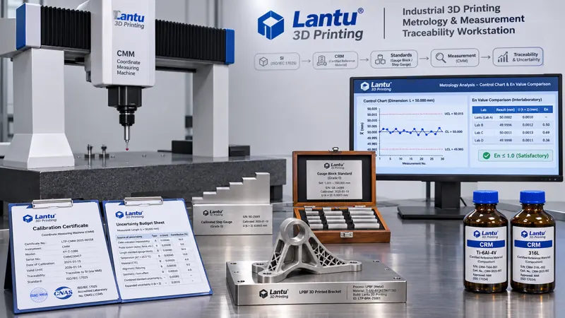
A complete chain is: SI units → national or defense metrology standards → certified reference materials/reference standards → working measuring instruments → part measurement results. Each level must retain the certificate number, calibration date, validity period, accreditation scope of the calibration provider, correction value, and expanded uncertainty. Typical traceability routes in a 3D printing facility include: coordinate measuring machines (CMMs) verified for E0 MPE under ISO 10360-2 using step gauges or ball-bar standards; calipers and micrometers checked with Grade 0/K gauge blocks under ISO 3650 and JJG 146; surface roughness testers checked with multi-groove specimens; powder particle-size analyzers using certified reference materials (GBW/ERM) with assigned D10, D50, and D90 values and expanded uncertainty; oxygen-nitrogen-hydrogen analyzers and ICP-OES instruments using composition CRMs; tensile testing machines using standard force-proving instruments under ISO 376 and JJG 139, Class 0.5 or 1; and hardness testers using certified hardness blocks. The most common break in the traceability chain is not the equipment itself, but treating “the certificate is still valid” as equivalent to “the instrument is currently fit for use.”
2. Calibration Certificate Verification: From Having a Certificate to Having a Usable Certificate
Five determinations should be completed upon receipt of a certificate. ① Competence and scope: confirm that the calibration provider is CNAS-accredited and that its accreditation schedule covers the calibration item, measurement range, and CMC. Data issued outside the accredited scope cannot be used for dispute resolution. ② Fitness for intended use: calibration certificates normally provide results rather than a pass/fail conclusion. The user must determine suitability against the maximum permissible error for the part being measured. The criterion is the ratio of expanded uncertainty U (k=2) to tolerance band T: generally, U ≤ T/3; for critical aerospace and medical characteristics, U ≤ T/10. For a hole diameter with T=0.05 mm, U should be ≤0.017 mm, or ≤0.005 mm under the T/10 rule. For a CMM with E0 MPE = 1.9 + L/350 µm, the value at L=100 mm is approximately 2.19 µm, leaving ample margin for U≤0.017 mm. By contrast, a caliper with 0.02 mm resolution clearly does not satisfy the requirement for measuring Ø8 ± 0.025 mm. Required U should first be derived from CTQs, then the equipment selected—not the reverse. ③ Confirm whether correction values have been entered into the compensation table or measurement program and independently reviewed by two people. ④ Confirm that the U stated on the certificate is included in uncertainty propagation. ⑤ Recalibration intervals should not be set uniformly at 12 months; they should be determined according to frequency of use, drift history, and risk level. Frequently used probes and force sensors should preferably be recalibrated every 6 months. It is recommended that certificate verification and filing be completed within five working days of receipt.
3. Reference Materials and Internal Quality-Control Samples: Bringing the Method into the Traceability System
Certified reference materials (CRMs), reference samples, and internal quality-control samples must be distinguished. CRMs are used for method validation, instrument calibration, and interim checks. Powder particle-size distribution, metal powder chemical composition, density reference blocks, and roughness specimens correspond to different CRM grades. Their lot number, certificate value, U, opening date, and expiration date must be recorded; the usable period after opening should be shortened according to the instructions. Internal quality-control samples must have the same material and process route as the tested parts, such as Ti6Al4V test coupons produced in the same LPBF build lot. They should be assigned unique retained-sample IDs, subjected to stability verification before use, and tested alongside every inspection batch. Interim checks are recommended every 20–30 batches or monthly, using X̄-R or XmR control charts to identify abnormalities. Any of the following triggers requires the measurement system to be taken out of service: one point beyond ±3σ, nine consecutive points on the same side of the center line, or six consecutive points showing a monotonic trend. All batches released since the last successful check must then be traced back; where necessary, they must be remeasured and customers notified. This step transforms traceability from “annual external calibration” into monitoring present in every batch.
4. Measurement Uncertainty Evaluation: Adding a Credible Interval to the Result
Apply GUM principles (JCGM 100 and JJF 1059.1): establish the measurement model → identify uncertainty components → obtain Type A uncertainty from repeatability tests (n≥10, u_A=s/√n) → derive Type B components from certificate U/k, resolution δ/√12, temperature deviation, fixturing and positioning, probe triggering and fitting algorithms, and number of sampling points → calculate combined standard uncertainty uc → apply k=2 (P≈95%) to obtain U → report as “Y = y ± U, k=2.” Using a Ø8.000 mm hole as an example: for 10 repetitions, s=0.0042 mm and u_A=0.0013 mm; the CMM certificate gives U=0.0025 mm, so u_B1=0.00125 mm; at 20±1 °C, a steel part with α=11.7×10⁻⁶/°C and L=8 mm contributes approximately 0.00009 mm, which is negligible; probe and fitting contribute u_B3=0.0018 mm; and fixturing contributes u_B4=0.0010 mm. The combined uncertainty is uc≈0.0027 mm, giving U≈0.0055 mm. Therefore, 8.019±0.0055 gives [8.0135, 8.0245], entirely within [7.975, 8.025], and may be accepted. In contrast, 8.028±0.0055 gives [8.0225, 8.0335], which partly exceeds the limit and falls within the uncertainty zone. It should not simply be rejected; instead, conformity should be determined using the conservative specification-limit-plus/minus-U rule of ISO 14253-1, or the part should be remeasured using a more accurate method. The opening dispute now has a solution: the disagreement is not an arithmetic problem, but the absence of U and a decision rule.
5. Interlaboratory Comparison and Proficiency Testing: Enabling Cross-Organization Data Recognition
For internal comparisons, measure the same part repeatedly using two CMMs, two operators, and different fixturing orientations. Use the En value to assess consistency: En = |x_lab − x_ref| / √(U_lab² + U_ref²), where |En| ≤ 1 is satisfactory. In the example above, x1=8.019 and U1=0.0055, while x2=8.028 and U2=0.0060; En = 0.009/0.00814 ≈ 1.11 > 1, indicating inconsistency. The traceability chain must be reviewed. In most cases, the cause is an unapplied correction value, different probe calibration, or missing temperature compensation. External proficiency testing should be organized in accordance with ISO/IEC 17043 and CNAS-RL02, with z-scores interpreted as follows: |z|≤2 satisfactory, 2<|z|<3 questionable, and |z|≥3 unsatisfactory, requiring corrective action. At least one PT exercise per year should be undertaken for critical characteristics. An additional comparison should be conducted after introducing a new test method, major equipment overhaul, relocation, or a change in key personnel. Comparison records must be archived together with the sample ID, evidence of sample homogeneity/stability, and certificate numbers used; otherwise, there is no evidence to support mutual recognition.
6. Data Integrity and the Record Chain: Applying ALCOA+ to Inspection Records
Raw records must contain more than a single result value. A CMM inspection must be traceable back to the measurement program version, raw point cloud or touch-point set, probe calibration file, ambient temperature and humidity (20±1 °C, RH 40%–60%), equipment unique ID and certificate number, CRM lot number and expiration date, correction-value application record, operator and reviewer, timestamp, and inspection report number. Electronic records must meet ALCOA+ requirements: attributable, legible, contemporaneous, original, accurate, complete, consistent, enduring, and available. Any remeasurement must create a new record and retain the reason for invalidating the prior result. Overwriting is prohibited, and all changes must retain an audit trail. Inspection reports and calibration certificate references must be traceable to original evidence through record numbers. In the chain from CTQ identification in drawing requirements to physical-part release, inspection data are the basis for release—not merely attachments shipped with the product.
7. Implementation Checklist and Common Pitfalls
Eight actionable checklist items are: ① establish a measuring-instrument register containing unique ID, certificate number, validity period, correction value, U, and the basis for the recalibration interval; ② derive required U from the CTQ tolerance band (T/3 to T/10) before selecting equipment; ③ complete the five certificate checks within five working days of receipt; ④ enter correction values into compensation tables and conduct two-person verification; ⑤ manage CRMs by category and record opening dates and expiration dates; ⑥ freeze released batches when interim-check control charts indicate abnormalities; ⑦ require reports to include U or at least state the conformity decision rule; and ⑧ conduct PT/interlaboratory comparison at least annually. Common pitfalls include treating “calibration passed” as “measurement passed”; confusing instrument resolution with measurement accuracy; overlooking contributions from temperature, fixturing, and fitting algorithms; conducting only internal comparisons without external proficiency testing; and using “more measurements and an average” to conceal systematic bias. These practices may make reports look more orderly, but leave the data unable to speak for themselves during a dispute.
Conclusion
Inspection data gain acceptance through a traceable, quantifiable, and mutually recognized chain—not through the nominal accuracy of a single instrument. By closing the loop among certificate verification, reference materials, uncertainty, proficiency testing, and record integrity, 3D printing delivery decisions can move from “we believe it conforms” to “any third party can recalculate the same conclusion.” This is the foundational work that enables lantu3D to connect technical requirements at the drawing stage with the evidence chain at the physical-delivery stage.
Submit a model, drawing, image or written notes. Engineers will review material, process, finishing and delivery based on actual use.