
Introduction: When Print Size, Material, or Cost Hits a Ceiling, Joining Becomes the Final Engineering Route
In project reviews for additive manufacturing, one type of requirement appears almost every week: the part outline exceeds the effective build volume of the machine, a local area requires material properties that cannot be obtained economically on a given printing system, or the machine-hour cost of printing the entire component has become unacceptable to the customer. What these three situations have in common is that they can no longer be solved by optimizing print parameters; instead, the answer must be found in the combination of manufacturing processes. Welding, brazing, and diffusion bonding are exactly the group of processes that are repeatedly used, yet often underestimated, when additive manufacturing moves from monolithic forming to combined manufacturing.
A real engineering scenario is as follows: a fluid distribution manifold measures 780 mm × 420 mm, exceeding the roughly 400 mm-class build envelope of mainstream laser powder bed fusion equipment; meanwhile, only two flange interfaces require high strength, while the rest of the body only needs pressure resistance and corrosion resistance. Printing the entire part would require large-format equipment and nearly a thousand hours of machine time. Printing it in sections and joining them by welding reduces the cost to less than one third of the original. The key to this type of decision is not whether the pieces can be welded, but whether the joint can pass subsequent pressure testing, inspection, and service qualification.
1. Why 3D-Printed Parts Cannot Simply Use Conventional Welding Procedures
Treating printed parts as ordinary forgings or castings during welding is one of the most common mistakes on the shop floor. Additively manufactured base material differs from conventional materials in three ways: it contains a certain proportion of internal pores and lack-of-fusion defects, its microstructure shows clear anisotropy and layer-by-layer characteristics, and it retains relatively high thermal stress after forming. These characteristics are amplified under the thermal cycle of welding.
Porosity is the most direct issue. Before hot isostatic pressing, laser powder bed fusion parts typically have a relative density of 99.5% to 99.9%. Under the high temperature of an arc or laser welding pool, residual micropores can expand and coalesce, forming pore chains distributed along the fusion line. In practice, the base material within 10 mm around the welding area is usually required to undergo hot isostatic pressing for densification, or industrial CT must be used during procedure qualification to confirm that the porosity in this region is below 0.2%. If this step is omitted, the first-pass acceptance rate in radiographic testing of the joint often drops from more than 90% to less than 60%.
Anisotropy affects the deformation behavior of the joint. Differences in thermal expansion coefficient and yield strength between the build direction, or Z direction, and the transverse direction cause asymmetric shrinkage under nonuniform welding heat, resulting in angular distortion of flange faces beyond tolerance. Common practice is to arrange weld beads symmetrically, use segmented back-step welding, and reserve counter-deformation in the fixture.
2. Process Families: Application Boundaries of Fusion Welding, Brazing, and Solid-State Bonding
When these three process categories are placed in the same decision table, the main criteria are joint strength requirements, metallurgical compatibility of the base materials, and allowable heat input.
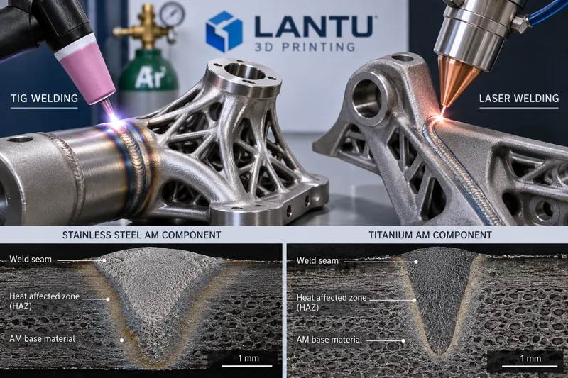
Fusion welding, including TIG, MIG, laser welding, and electron beam welding, relies on the melting of both base material and filler metal to form common grains. Joint strength can approach that of the base metal, making it suitable for load-bearing structures and pressure-vessel-type components. Its trade-offs are a large heat-affected zone, significant deformation, and high requirements for base-metal weldability. For printed 316L stainless steel parts, TIG welding with ER316L filler wire, heat input controlled at 0.8 to 1.2 kJ/mm per pass, and interpass temperature kept below 150°C can typically achieve joint tensile strength above 90% of the base material.
Brazing uses a filler metal with a melting point lower than that of the base material to fill the joint gap by capillary action, while the base material itself does not melt. The heat-affected effect is minimal, making it suitable for precision parts, thin-walled parts, and dissimilar-material combinations. Silver-based brazing alloys, such as BAg series fillers, have brazing temperatures of 600 to 800°C, and vacuum brazing or protective-atmosphere brazing can prevent oxidation. The limitation is that joint strength is governed by the strength of the brazing filler itself and by gap control: strength is highest when the brazed seam gap is between 0.05 and 0.15 mm, while excessive gaps cause a sharp strength decline. This is why brazed-joint design must clearly specify fit tolerances.
Diffusion bonding and solid-state joining, such as diffusion welding and friction stir welding, lie between the two. Diffusion bonding applies pressure in vacuum or an inert atmosphere and holds the parts at 0.5 to 0.7 times the melting point, forming filler-free joints through atomic diffusion with almost no heat-affected zone. It is a preferred option for joining printed titanium alloy and superalloy components. Typical parameters are 900 to 950°C, pressure of 5 to 10 MPa, and holding time of 60 to 120 minutes.
3. Key Implementation Points for Joining Similar Metals
Taking the most common printed titanium alloy, Ti6Al4V, as an example, three preparations must be completed before welding. The first is surface cleaning: partially melted particles and oxide layers attached to the printed surface must be removed from the welding area by mechanical grinding or chemical milling to expose metallic luster, and the grinding range should extend more than 15 mm beyond the groove edge. The second is groove design: for plate thicknesses above 6 mm, a V-groove or X-groove is recommended, with a root face of 1 to 2 mm to ensure root penetration. The third is atmosphere protection: titanium alloys strongly absorb oxygen, nitrogen, and hydrogen above 400°C, so the weld and heat-affected zone must be protected on both sides with argon of at least 99.999% purity. A trailing shield should be used to protect the high-temperature area until it cools below 400°C. A silver-white or pale-yellow weld color is acceptable; blue or gray indicates excessive oxidation and requires cutting out and rewelding.
The difficulty with printed aluminum alloy parts lies in hydrogen porosity. Printed AlSi10Mg has a high silicon content, and the weld pool tends to absorb hydrogen during welding. The base material should therefore be preheated to 120 to 150°C for moisture removal before welding, ER4043 filler wire should be selected to reduce hot-cracking sensitivity, and the shielding gas dew point must be strictly controlled below -40°C.
4. Dissimilar-Material Transition Joints: From Steel-Aluminum to Copper-Stainless Steel
Joining printed parts with conventionally manufactured components is one of the fastest-growing demands as additive manufacturing enters engineering applications. The core challenge is metallurgical incompatibility: direct fusion welding of steel and aluminum produces a brittle intermetallic compound layer, and when its thickness exceeds 10 μm, the joint has almost no ductility.
The mainstream engineering solution is to use transition joints. A layer of metal compatible with aluminum, such as pure aluminum or an aluminum-silicon alloy, is first deposited on the steel side by cladding or formed by explosive bonding. Brazing or fusion welding is then performed on the aluminum side over the transition layer, confining the brittle compounds to the composite interface rather than the weld seam. For copper-stainless steel combinations, nickel-based filler metals are typically used, or a nickel layer is pre-plated on the copper side to suppress penetration cracking caused by copper entering steel grain boundaries.
Another more robust approach is to avoid fusion welding: design a hybrid joint that combines mechanical fastening with brazed sealing between dissimilar materials. The mechanical structure carries the load, while the brazed layer is responsible only for sealing. This design decouples metallurgical risk from the load-bearing function and is widely used in pressure-vessel pipe connections, though it results in a slightly heavier structure and additional assembly steps.
5. Joint Quality Validation and Release Criteria
Welded and brazed joints cannot be released based on appearance alone. A complete validation program should cover four levels: appearance and dimensions, including weld reinforcement, angular distortion, and brazed-seam fill rate; nondestructive testing, with fusion-welded joints inspected by radiography or ultrasonic testing and brazed joints mainly by ultrasonic and leak-tightness testing, while industrial CT is recommended for printed-part weld zones to check pore clustering; mechanical validation, including tensile, bend, and impact tests on procedure qualification coupons from the same batch; and service validation, including hydrostatic testing at 1.5 times the working pressure with a hold time of no less than 30 minutes.
Procedure qualification should be completed before mass production and documented as a welding procedure specification, locking in current, voltage, heat input, interpass temperature, shielding-gas flow rate, and post-weld heat-treatment curves. Without this step, every weld becomes an uncertain experiment, and rework costs will quickly consume the time advantage originally gained through additive manufacturing.
6. Joint Design Recommendations for Additive Manufacturing
Rather than remedying problems at the process stage, it is better to account for joining during design. Three specific recommendations are useful: first, place welds in low-stress areas, avoiding section transitions and fatigue-sensitive locations; second, directly print welding location shoulders and brazing-filler grooves on the part to reduce alignment time during assembly and ensure consistent gaps; third, clearly specify whether stress-relief annealing is required after welding. Titanium alloys are usually held at 600 to 700°C for 1 to 2 hours, while aluminum alloys more often use low-temperature annealing at 250 to 300°C. Incorrect parameters can directly cause dimensional nonconformance or performance degradation.
Conclusion
Welding, brazing, and diffusion bonding are not substitutes for additive manufacturing, but engineering tools that release it from the size limits of a single machine. Which process to choose depends on joint strength requirements, metallurgical compatibility of the base materials, and allowable heat input. Whether stable qualification can be achieved depends on the densification state of the base material, surface-cleaning quality, atmosphere protection, and the completeness of procedure qualification. When these prerequisites are properly addressed, combined manufacturing can capture the geometric freedom of additive manufacturing while preserving the reliability baseline of the structure.
Submit a model, drawing, image or written notes. Engineers will review material, process, finishing and delivery based on actual use.