
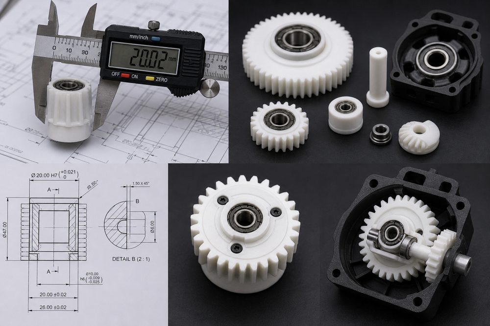
Core Logic of 3D-Printed Assembly Tolerance Design: Evaluate Process Capability First, Then Define the Fit
Tolerance design for 3D-printed assemblies cannot simply follow the traditional hole-shaft fit approach used in machining. The reason is that dimensional error in printed parts comes from more sources: not only machine positioning accuracy, but also material shrinkage, layer stacking, cross-sectional anisotropy, and deformation during post-processing. Taking common FDM as an example, in an uncompensated state, dimensional error is typically around ±0.2 mm to ±0.5 mm; hole diameter error is often larger than external dimensions, and an internal hole being 0.1 mm to 0.4 mm undersized is not uncommon. SLA photopolymer printing can achieve ±0.05 mm to ±0.15 mm on small parts, but post-curing and support removal can introduce secondary deformation. When designing fits, the key is to define the process capability envelope first, then work backward to shaft diameter, hole diameter, and clearance, rather than ordering parts directly from mechanical drawing dimensions.
- For conventional FDM, evaluate dimensional accuracy at ±0.2 mm to ±0.5 mm, and leave more allowance for hole locations.
- SLA is suitable for fine fits, but post-cure shrinkage and local warpage must be considered.
- Tolerance design should be based on the combined error of process capability + material shrinkage + post-processing deformation.
Design Standards for Hole-Shaft Fits: Handle Rotating, Locating, and Detachable Scenarios Separately
Hole-shaft fits are the most common feature in 3D-printed assemblies, but also one of the most failure-prone. If the goal is a rotating fit, such as for shafts, hinges, or gear shafts, it is recommended to leave a single-sided clearance of 0.15 mm to 0.30 mm. For holes printed by FDM, considering inward hole shrinkage and layer-line roughness, the hole diameter is generally recommended to be 0.3 mm to 0.6 mm larger than the shaft diameter. If the goal is a locating fit that is still detachable, such as a dowel pin and guide hole, the single-sided clearance can be controlled within 0.05 mm to 0.15 mm, provided that SLA or high-accuracy SLS is used and the hole axis is oriented vertically as much as possible to reduce roundness error. With ordinary FDM equipment, a locating hole designed with 0.1 mm clearance will usually result in assembly interference and require secondary drilling or reaming.
In practical engineering, a shaft-diameter grading method can be used: for small shafts below 3 mm, FDM is recommended to use a total hole-shaft clearance of 0.25 mm to 0.40 mm; for small-to-medium shafts from 3 mm to 10 mm, a total clearance of 0.30 mm to 0.60 mm is recommended; for large shafts above 10 mm, a total clearance of 0.50 mm to 1.00 mm is recommended, because roundness error and local thermal deformation in printed parts increase with size. For example, with a 12 mm shaft in a nylon SLS part, if the design uses only 0.1 mm total clearance, the part may fit but feel sticky when rotating. After increasing the clearance to 0.4 mm, rotation becomes smooth while axial play remains acceptable.
- Rotating hole-shaft fits: FDM total clearance 0.30 mm to 0.60 mm; SLA can be reduced to 0.15 mm to 0.30 mm.
- Locating pin holes: prioritize SLA/SLS, with a recommended single-sided clearance of 0.05 mm to 0.15 mm.
- The smaller the hole diameter, the greater the compensation required; small holes should leave at least 0.2 mm of post-machining allowance.
Engineering Values for Sliding Clearance: Ensure Smooth Motion While Controlling Play and Jamming
Sliding fits are the most common design target for linear guides, sliders, drawer-style mechanisms, and detachable housings. The sliding clearance of a 3D-printed part should not be judged by nominal dimensions alone; surface roughness and material elasticity must also be considered. Common FDM surface roughness is around Ra 6.3 μm to 25 μm, and layer lines can make the actual friction on the contact surface higher than what geometry alone suggests. SLA and MJF surfaces are finer, but SLA is relatively brittle, and local indentation can also affect sliding performance. In engineering practice, the single-sided clearance for FDM sliding fits should be no less than 0.2 mm, preferably 0.25 mm to 0.4 mm; SLA can be controlled at 0.1 mm to 0.2 mm; and SLS/MJF nylon parts can be designed in the 0.15 mm to 0.3 mm range. For long-stroke guide structures, it is recommended to add a chamfer or lead-in angle along the direction of motion; typically 0.5 × 45° to 1 × 45° is enough to significantly reduce first-assembly resistance.
A common case is a sliding cover in an equipment enclosure printed in FDM ABS. The initial clearance was set to 0.15 mm, and after assembly the part showed local jamming and local looseness. Disassembly revealed that the print orientation caused slight inward bowing of the side walls, and the actual effective clearance at some locations was only 0.03 mm. After increasing the clearance to 0.35 mm and reorienting the contact surfaces to run along the layer lines, sliding resistance dropped by about 40%, and assembly rework was significantly reduced. For mechanisms that need repeated sliding over a long service life, it is recommended to add another 0.05 mm of clearance as wear allowance.
- FDM sliding fits: recommended single-sided clearance of 0.2 mm to 0.4 mm.
- SLA sliding fits: recommended single-sided clearance of 0.1 mm to 0.2 mm.
- Long-stroke guide surfaces should include a lead-in chamfer to reduce scraping during first assembly.
Design Limits for Press Fits: 3D Prints Should Not Be Forced to Follow Metal Press-Fit Logic
Press fits are commonly used in metal parts to retain bearings, bushings, and locating sleeves, but they must be treated very cautiously in 3D-printed parts. The elastic modulus, interlayer strength, and thermal stability of printed materials are all inferior to metal, especially for FDM PLA and PETG, where excessive press-in force can cause hole-wall cracking, local delamination, or permanent deformation. If a light press fit must be achieved, it is recommended to prioritize SLS nylon, MJF nylon, or reinforced materials, and keep the interference within a small range. In practice, the single-sided interference for FDM parts is not recommended to exceed 0.05 mm to 0.10 mm, and it is better suited to use with metal inserts or heat-set threaded inserts. For SLS nylon, a single-sided interference of 0.05 mm to 0.15 mm can be considered. SLA resins are usually only suitable for very slight interference, and anything above 0.05 mm carries a cracking risk.
For example, in an 8 mm-diameter bearing seat printed in PA12 SLS, if the nominal outer diameter of the bearing is 8.00 mm and the hole is initially designed to be 7.90 mm, installation is smooth and positioning remains stable. If the hole is reduced to 7.80 mm, installation force rises significantly, and after repeated thermal cycling the hole wall creeps and the bearing outer ring loosens. For scenarios that require reliable retention, a more robust method is to use a printed pilot hole + heat-set metal insert + adhesive assistance, rather than allowing the printed part to bear long-term, high-stress press-fit loads directly.
- FDM press fits: recommended single-sided interference ≤0.05 mm to 0.10 mm, and direct bearing press-in should be avoided where possible.
- SLS/MJF nylon: single-sided interference can be relaxed to 0.05 mm to 0.15 mm, but long-term stability must be verified.
- SLA resins are not suitable for large-interference press fits; adhesive bonding or insert structures are preferred.
Material Shrinkage and Print Orientation: The Same Dimension Must Be Calibrated Separately for Different Processes
3D-printing tolerance design cannot be separated from material shrinkage. PLA typically has relatively low linear shrinkage, usually controllable within 0.2% to 0.5%. ABS and ASA may reach 0.5% to 1.0%, and larger parts can be even higher. PA12 in SLS/MJF generally requires process compensation based on 1.0% to 2.0% overall shrinkage, but this shrinkage is more often reflected in the combined calibration of the machine and material batch. Even more critical is the print orientation: dimensional error in the Z direction is usually greater than in the XY plane, and hole roundness also worsens as layers build up. For large holes above 20 mm in diameter, if the hole axis is parallel to the Z direction, oval holes or stepped holes often appear. In such cases, even if the nominal dimension is correct, the assembly experience can still deviate significantly.
In engineering practice, a direction-priority principle can be used: when high-precision hole diameters are required, place the hole axis in the XY plane as much as possible; when high axial load-bearing strength is required, adjust the orientation according to structural needs and correct the hole size through post-machining. If the process is fixed, first-article calibration is recommended. For example, print five sets of hole compensation values on the same build platform: +0.1 mm, +0.2 mm, +0.3 mm, +0.4 mm, and +0.5 mm. After measurement, choose the compensation value closest to the target fit and apply it in batch production. This approach is more reliable than relying solely on the software’s default compensation, especially when switching to a new material, a new machine, or a new supplier.
- PLA shrinkage is usually small; ABS/ASA require more compensation; PA12 should be calibrated based on the machine.
- Keep hole axes in the XY plane as much as possible to reduce the effect of Z-direction stair-stepping on roundness.
- At least five compensation levels should be tested during first-article calibration; do not move directly into mass production.
Typical Design Values and Cases: Put Tolerances on the Drawing to Avoid Assembly Rework
In real projects, the most effective approach is to convert fit requirements into actionable drawing values. A practical set of reference values is as follows: for general FDM assembly features, a free clearance of 0.2 mm to 0.3 mm is recommended; for FDM screw holes, the hole diameter is usually 0.3 mm to 0.5 mm larger than the screw diameter. An M3 through-hole in FDM is commonly designed at 3.4 mm to 3.6 mm, while in SLA it can be designed at 3.2 mm to 3.3 mm. An M5 locating hole in SLS nylon can be designed at 5.15 mm to 5.30 mm, and if it is used for pin location and must insert smoothly, it is recommended to trial start at 5.20 mm. For embedded metal parts, hole accuracy requirements are higher; the hole diameter should ideally leave 0.05 mm to 0.15 mm relative to the insert outer diameter, and press-in force should be confirmed through a hot-fit test.
In one automation fixture project, an SLA-printed locating plate was used. In the original design, eight dowel-pin holes were output directly at the nominal 8.00 mm size, and only three of the holes could be assembled smoothly; the others required manual reaming. After a review, the hole diameter was uniformly changed to 8.18 mm, and the print orientation was adjusted so that the hole axis was parallel to the build platform. The first-pass assembly success rate increased to over 95%, and fixture ...
Submit a model, drawing, image or written notes. Engineers will review material, process, finishing and delivery based on actual use.