
lantu3D

Engineering Specifications for Connector Design in 3D Printed Parts: Snap-Fits, Hinges, and Embedded Fasteners

Connector design for 3D printed parts is one of the most practical areas in additive manufacturing. Unlike conventional manufacturing, 3D printing can integrate snap-fits, hinges, and embedded fasteners directly into the part, enabling true design-for-assembly and reducing assembly time, part count, and reliability risks. However, successful connector design requires a deep understanding of material behavior, process limitations, anisotropy, support removal, and post-processing effects. This article outlines engineering specifications and design rules for snap-fits, hinges, and embedded threaded inserts in FDM and SLA printing.
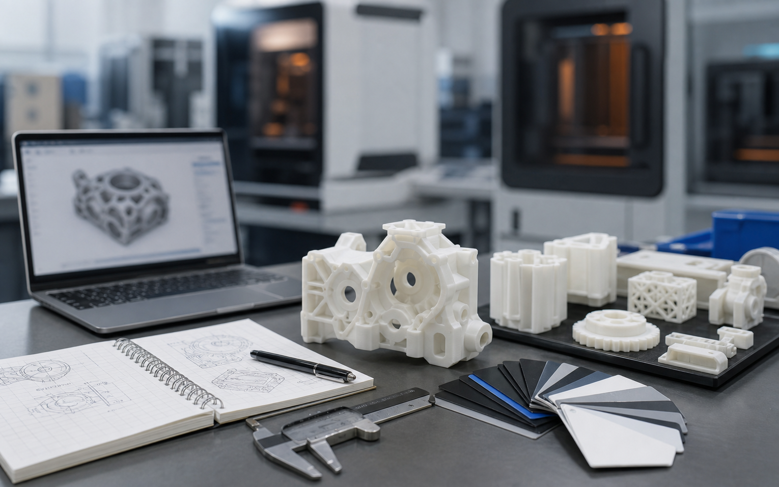
Engineering Specifications for Connector Design in 3D Printed Parts: Snap-Fits, Hinges, and Embedded Fasteners
# Engineering Specifications for Connector Design in 3D Printed Parts: Snap-Fits, Hinges, and Embedded Fasteners ## Introduction: The Special Significance of Connector Design in 3D Printing Connector design is one of the most practical areas in 3D printed part design. In traditional manufacturing, part-to-part connections usually rely on secondary assembly processes such as screws, welding, and adhesives. These methods not only increase process complexity, but can also become weak links in product reliability. One of the greatest advantages of 3D printing is that it can directly form snap-fits, hinges, embedded fasteners, and other connection structures as part of the component in a single build, enabling integrated manufacturing with true "design equals assembly" logic. According to industrial design statistics, properly applied 3D printed connector design can reduce assembly time by 40-60%, reduce total part count by 30-50%, and improve overall product reliability. However, 3D printed connector design is not just simple geometric modeling. It is a complex systems engineering task that requires a deep understanding of material properties, process constraints, mechanical performance, and long-term service reliability. Layer orientation, material anisotropy, residual support structures, and post-processing effects can all significantly affect the real-world performance of a connector. A poorly designed connector may fail on first use, or develop fatigue cracks during long-term service. Therefore, it is crucial to establish scientific design specifications for 3D printed connectors. ## Core Principles and Engineering Calculations for Snap-Fit Design Snap-fits are the most commonly used joining method in 3D printing. Their principle is to use elastic deformation for quick assembly and locking. A successful snap-fit design requires precise calculation of deflection, retention force, and separation force. **Snap-fit type selection** - Cantilever snap-fit: best suited for 3D printing, easy to produce, and mechanically predictable - Annular snap-fit: suitable for cylindrical part connections, but often requires more support - Torsional snap-fit: suitable for planar assembly, but the twist angle must be tightly controlled - Ball-and-socket snap-fit: suitable for multi-directional assembly, but requires high print accuracy **Cantilever snap-fit design formula** The retention force F of a cantilever snap-fit is calculated as: F = (E × b × t² × y) / (6 × L³) where: - E: elastic modulus of the material (MPa) - b: snap width (mm) - t: snap thickness (mm) - y: deflection amount (mm) - L: cantilever length (mm) **Reference elastic modulus values for 3D printing materials** - PLA: 3200-3500 MPa - ABS: 2100-2400 MPa - PETG: 2000-2200 MPa - TPU (85A): 20-50 MPa - Nylon PA12: 1700-1900 MPa - Resin (standard): 2500-3000 MPa **Snap-fit geometric design guidelines** 1. Snap thickness t: should be 50-80% of the connecting wall thickness 2. Cantilever length L: recommended L/t ratio is 5-10 3. Lead-in angle: 30-45° to reduce insertion resistance 4. Retention angle: 15-30° to ensure reliable locking 5. Root fillet radius: R ≥ t to avoid stress concentration 6. Free clearance: 0.2-0.5 mm to compensate for printing errors **Special considerations for FDM-printed snap-fits** The layer orientation of FDM printing has a major impact on snap-fit strength. The loading direction of the snap-fit should be parallel to the layer direction (force applied along the Z-axis) to avoid interlayer delamination. If the snap-fit must withstand bending stress, the bending direction should be designed perpendicular to the layers (with the layers parallel to the snap length direction) to make use of the material's longitudinal strength. **Advantages and limitations of SLA-printed snap-fits** SLA-printed snap-fits have smooth surfaces and high dimensional accuracy, but resin materials are brittle and are not suitable for snap-fits requiring large deformation. Tough resins (such as engineering resins and elastic resins) are recommended, and the deflection should be controlled within 10% of the wall thickness. ## Material Selection and Life Prediction for Hinge Design 3D printed hinges can achieve true integrated moving joints without any additional assembly parts. However, hinge design places very high demands on material selection and geometric accuracy. **Principle of integral hinge design** An integral hinge is formed by locally reducing material thickness to create a flexible connection region. When the hinge area is thin enough, the material can undergo elastic or plastic deformation to provide opening and closing motion. Key parameters: - Hinge thickness: 0.3-1.0 mm (depending on material) - Hinge length: at least 3-5 times the thickness - Transition fillet radius: R ≥ 2 times the thickness **Material selection guidelines** - PLA: not suitable for hinges, brittle and prone to fracture ( 1000 cycles 4. If ε is between 0.5 and 0.8 times the allowable strain, expected life is 100-1000 cycles 5. If ε > 0.8 × allowable strain, expected life < 100 cycles **Dimensional advantages of SLA-printed hinges** SLA can produce hinge thicknesses of 0.3 mm or even thinner, with smooth surfaces and no visible layer lines, making it the preferred process for precision hinges. However, moisture absorption and aging of the resin must be considered, as toughness decreases over time. ## Design and Installation Specifications for Embedded Fasteners Embedded fasteners (heat-set inserts, molded-in nuts, etc.) are the best solution for achieving high-strength, removable connections in 3D printed parts. By embedding metal threaded elements into plastic parts, it is possible to obtain thread strength close to that of metal components. **Selection of embedded fastener types** 1. Heat-set inserts: best suited for 3D printing, easy to install, and high pull-out strength 2. Molded-in inserts: must be pre-embedded during printing and require high precision 3. Self-tapping screws: screwed directly into plastic, but with lower strength 4. Metal threaded bushings: used for high-load applications, but require more installation space **Heat-set insert hole design** The installation hole for a heat-set insert is critical: - Hole diameter: 0.1-0.2 mm smaller than the insert outer diameter (interference fit) - Hole depth: 0.5-1.0 mm deeper than the insert length (to accommodate overflow material) - Entry chamfer: 1 × 45° to guide the insert in - Internal wall texture: longitudinal grooves are recommended (0.5 mm wide, 0.3 mm deep) to improve anti-rotation performance **Precautions for FDM-printed mounting holes** The inner wall of FDM-printed holes has spiral layer lines, which reduces insert retention strength. Improvements include: 1. Leave a 0.2 mm allowance in the hole diameter, and use a soldering iron after installation to melt plastic and fill the gap 2. Add a shallow recess at the hole opening (0.5 mm deep) to collect molten plastic overflow 3. Use a hexagonal hole instead of a round hole to prevent the insert from rotating **Precision control for SLA-printed mounting holes** SLA-printed holes are highly accurate, but resin curing shrinkage may reduce the hole diameter. Recommended practices: - Increase hole diameter by 0.1-0.15 mm to compensate for shrinkage - Avoid deep holes (>10 mm) because powder removal becomes difficult - Use support structures to ensure hole wall verticality **Installation process specification** Heat-set insert installation steps: 1. Place the insert above the mounting hole 2. Use a dedicated soldering tip matching the insert outer diameter and heat it to 200-220°C 3. Press the insert vertically into the hole and maintain pressure until the plastic cools (about 5-10 seconds) 4. Check whether the insert is flush and whether any overflow material has entered the threads 5. Clean the threads with compressed air **Pull-out force and torque test standards** Performance verification of embedded fasteners: - Pull-out force test: axial tensile force should be >200 N (M3 insert), >400 N (M4 insert) - Torque test: tightening torque should reach
Next Step Is this close to what you need?

Submit a model, drawing, image or written notes. Engineers will review material, process, finishing and delivery based on actual use.

Submit Request Ask First