
Introduction: When Parts Need to Be “Assembled” Rather Than “Printed as One Piece”
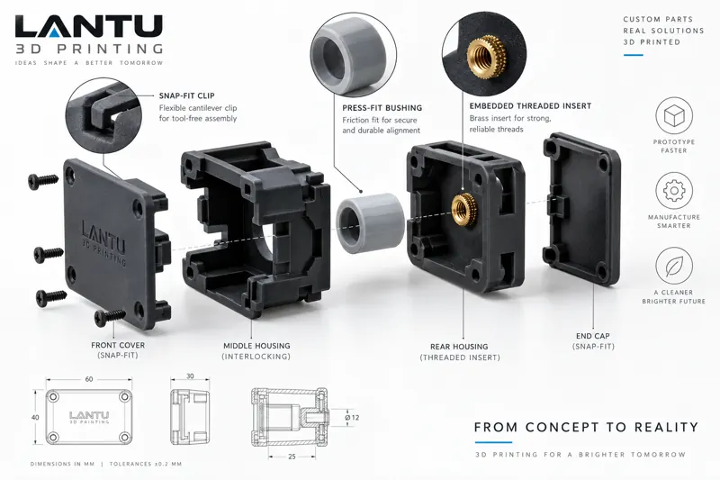
3D printing is often regarded as synonymous with “forming complex single parts in one process,” but in real engineering applications, more products are assembled from multiple printed parts, or from printed parts together with standard components—such as the body and pressure block of a medical fixture, the housing and gears of a robotic end effector, or the exterior cover and internal bracket of consumer electronics. In these cases, the printability of a single part is only the first step. The real challenge is whether multiple parts can interlock precisely, reliably, and repeatedly. Design for Assembly (DFA) is often overlooked in low-volume 3D printing: designers focus on the geometric complexity of individual parts, but end up with broken snap-fits, cracked interference fits, or stripped threads, eventually relying on manual sanding and glue as remedies. This not only sacrifices the rapid iteration advantage of 3D printing, but also introduces risks to batch consistency. This article starts with the three most typical connection methods—snap-fits, interference fits, and threaded connections—and provides practical engineering parameters and design constraints.
1. Selection Logic for Assembly Connection Methods
Before selecting a connection method, answer three questions: Does the assembly need to be repeatedly disassembled? What load and torque must it withstand? Is adhesive bonding or post-processing allowed? Based on this, common solutions can be divided into four categories. Snap-fits are suitable for tool-free quick assembly of plastic parts, light loads, and one-time or limited disassembly. Interference fits are suitable for shaft-hole positioning, bearing press-fitting, and bushing retention, relying on material elasticity. Threaded connections, including embedded nuts and printed threads, are suitable for applications requiring high clamping force, repeated disassembly, or tensile and torsional load resistance. Structural adhesive bonding is used for dissimilar materials, large-area bonding, or sealing. SLS nylon (PA12) and MJF parts are preferred for snap-fits and interference fits because of their good toughness and elastic recovery. Photopolymer resins used in SLA/DLP are more brittle, with high elastic modulus but low elongation at break, so snap-fits can easily fracture and should be used with caution. Metal SLM parts have high strength but limited elastic recovery, so interference must be strictly controlled; otherwise, cracking may occur during press-fitting.
2. Process Constraints for Snap-Fit Design
Cantilever snap-fits are the most commonly used structure. The maximum bending stress at the root is inversely proportional to the cube of cantilever length L and directly proportional to the cube of wall thickness t. Therefore, it is better to thicken the root and shorten the cantilever than to rely on a long, thin-walled feature for springback. As a rule of thumb, the cantilever thickness of PA12 snap-fits should be 1.5–2.5 mm, and the root fillet should be R≥0.5 mm to avoid stress concentration. The draft angle, or deflection release angle, must ensure that the snap-fit does not undergo permanent deformation after assembly deflection. For PA12, the allowable deflection is approximately 1.5–2 times the wall thickness. The SLS build orientation has a significant impact on snap-fit strength: if the bending direction of the snap-fit is parallel to the layer lines, interlayer bonding becomes the weakest plane. The main bending stress should therefore be oriented perpendicular to the layer direction. For resin snap-fits, trapezoidal snap structures or larger transition fillets are recommended, and the maximum deflection should be limited to within 60% of the material’s elongation at break.
3. Interference Fits and Press-Fit Calculation
Interference fits generate contact pressure through elastic deformation to achieve positioning or torque transmission. The press-in force can be estimated as F≈π·d·L·p·μ, where d is the mating diameter, L is the mating length, p is the contact pressure, and μ is the coefficient of friction. For PA12, μ≈0.3. The interference amount is generally 0.1%–0.5% of the diameter. For example, a φ10 shaft-hole fit would use 0.01–0.05 mm interference. For metal parts, 0.05%–0.2% is typical. The key pitfall is dimensional shrinkage in 3D printing: SLS parts shrink differently in the Z direction and XY plane, and nylon parts generally shrink by about 2%–4%. Shrinkage compensation must be applied in the digital model before interference is added. SLM metal parts have linear shrinkage of about 0.1%–0.3%, but residual stress can cause slight deformation. Therefore, the interference should be on the smaller side and combined with reaming or precision machining. During press-fitting, insertion speed and end guiding chamfers, such as 0.5×45°, should be controlled to avoid edge galling or damage.
4. Threaded Connections: Embedded Nuts vs. Printed Threads
When repeated disassembly or tensile and torsional loads are required, embedded nuts should be prioritized over directly printed threads. Heat-set brass inserts can be embedded into SLS nylon parts by ultrasonic insertion or thermal pressing, providing much higher pull-out strength and torque resistance than printed threads. For M3 inserts, an embedding depth of ≥4 mm and surrounding wall thickness of ≥2 mm are recommended to prevent cracking. Directly printed threads are limited by layer lines and dimensional accuracy: the minimum recommended internal thread size is M3–M4, as smaller sizes are prone to missing thread profiles; the pitch should be no less than 0.5 mm; the thread must be printed along the Z direction, with 0.1–0.2 mm tapping allowance reserved for manual or machine tapping. External threads can be printed down to M2.5, but machining allowance should be left for subsequent turning. For metal SLM threads, “printed pilot hole + subsequent tapping” is also recommended. Fully printed threads are unreliable in fatigue or sealing applications. Regardless of the method, reinforcing ribs should be designed around the nut seat to distribute clamping stress.
5. Assembly Clearance, Positioning, and Error-Proofing
Clearance must be reserved for movable mating surfaces: for plastic parts at room temperature, the clearance is typically 0.1–0.3 mm; for metal parts, it is 0.05–0.15 mm. If the clearance is too small, parts may seize due to positive printing dimensional deviation and thermal expansion. Positioning should preferably use a “one plane and two pins” approach, or a combination of locating posts and locating holes. The locating post diameter should be 0.1–0.2 mm smaller than the hole. Sliding fits require tighter tolerance bands and possible post-processing such as reaming or sanding. Error-proofing, or poka-yoke, has very low cost in low-volume 3D printing: asymmetric locating features, a unique guide slot, or raised text such as “TOP” and direction arrows can prevent incorrect assembly. All mating features should be toleranced at the CAD model stage rather than relying on trial fitting after post-processing.
6. Coordination Between DFA and the Printing Process
Assembly-friendly design often works in synergy with printability rather than conflicting with it. Placing snap-fits, nut seats, and locating posts on the same datum surface allows shared support strategies and inspection fixtures. The assembly direction should align with the printing direction as much as possible to reduce support damage to mating surfaces. For interference and threaded features, leaving 0.5–1 mm of machining allowance around them and finishing them in one setup after printing provides better consistency than relying on printing alone. It is recommended to establish an “assembly feature checklist”: snap-fit root fillets, interference compensation values, nut seat wall thickness, threaded pilot hole allowance, moving clearances, and error-proofing marks. During first article inspection (FAI), each item should be measured so that assembly qualification shifts from “based on feel” to “quantifiable.”
Conclusion
Assembly design for 3D printing is not about directly copying conventional machining rules. Instead, it requires trade-offs among material elasticity, printing shrinkage, layer orientation, and post-processing capability. For snap-fits, focus on wall thickness and draft angle; for interference fits, focus on shrinkage compensation and interference amount; for threads, prioritize inserts and pilot hole allowance. With reasonable clearance and error-proofing added, multi-part products can move from “printable” to “reliably assembled.” Incorporating assembly features into first article inspection is a key step toward improving delivery quality in low-volume 3D printing.
Submit a model, drawing, image or written notes. Engineers will review material, process, finishing and delivery based on actual use.