
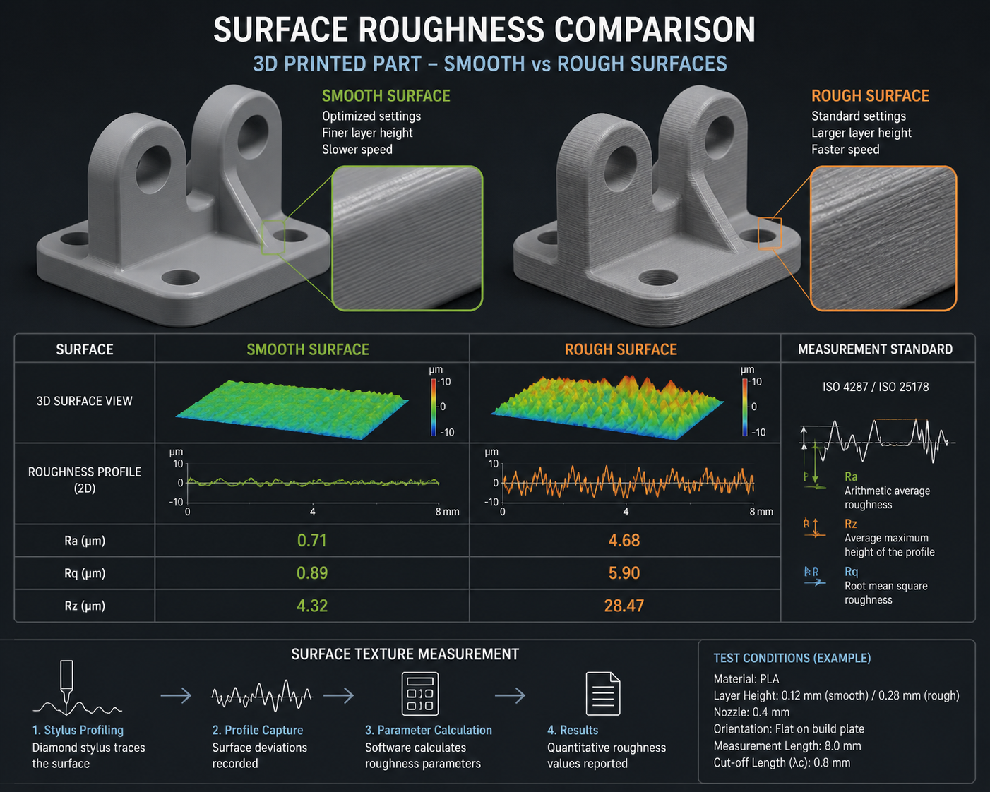
Introduction: Surface quality determines the function and appearance of 3D printed parts
Surface roughness is one of the key indicators for evaluating the quality of 3D printed parts, which directly affects the functional performance (such as friction and wear, sealing, fatigue life) and appearance quality of the part. Compared with traditional machined surfaces (Ra 0.4-1.6μm), the original surface of 3D printed parts is usually rougher. The surface roughness of the FDM process can reach Ra 15-50μm, the SLS process is Ra 8-20μm, and the SLM metal printing is Ra 5-15μm. This gap in surface quality has become one of the important obstacles for 3D printed parts to move from prototypes to terminal applications.
However, surface quality control is not an insurmountable gap. Through reasonable process selection, printing parameter optimization and scientific post-processing process, the surface quality of 3D printed parts can be significantly improved to meet the needs of most engineering applications. This article will systematically introduce the causes, measurement methods, control strategies and post-processing technology of 3D printing surface roughness, providing a reference for enterprises to establish a complete surface quality control system.
Causes and influencing factors of surface roughness
The surface roughness of 3D printed parts is mainly determined by process characteristics. Taking the FDM process as an example, layer thickness is the primary factor affecting surface roughness. The larger the layer thickness, the more obvious the surface step effect and the higher the roughness. Parameters such as nozzle diameter, extrusion flow rate, printing speed, and extrusion temperature also affect surface quality. In addition, the angular relationship between the part surface and the printing platform determines the degree of step effect: the step effect is most obvious on the slope at an angle of about 45 degrees to the Z-axis, and the roughness of the horizontal and vertical surfaces is relatively low.
The surface roughness of the SLS/SLM powder bed process is mainly determined by the powder particle size, laser power and scanning strategy. The larger the particle size of the powder, the rougher the surface; excessive laser power will cause surface spheroidization and produce irregular bulges. SLM metal printing also has problems such as smoke deposition and spatter particle adhesion, which further deteriorates the surface quality. The surface quality of the SLA light-curing process is usually the best, but it is still affected by the layer thickness, exposure time and resin viscosity. The surface may have corrugated stripes (caused by squeegee movement) or microbubble defects.
Material properties also affect surface quality. The printed surface of particle-filled composites (such as glass fiber reinforced nylon, carbon fiber reinforced materials) is usually rougher because the filler particles are exposed on the surface. The sphericity, particle size distribution and fluidity of metal powder also affect the printing surface quality. In addition, external factors such as the printing environment (temperature, humidity) and machine status (nozzle wear, platform flatness) cannot be ignored. A comprehensive understanding of these influencing factors is the prerequisite for formulating effective surface quality control strategies.
Measurement and evaluation methods of surface roughness
The measurement methods of surface roughness are divided into two categories: contact and non-contact. Contact measurement (stylus roughness meter) records the contour curve by moving the probe on the surface and calculates Ra and Rzand other parameters, suitable for hard material surfaces. However, stylus measurement may scratch the surface of soft materials, and for 3D printing surfaces that are porous or have complex textures, the stylus may fall into the pores, causing measurement errors. Non-contact measurement includes white light interferometer, confocal microscope, laser confocal, etc., which can achieve accurate measurement of three-dimensional surface topography and is suitable for complex surfaces and porous structures.
For 3D printed parts, it is recommended to use a three-dimensional surface measurement method, because only measuring the Ra value cannot fully reflect the surface characteristics. Three-dimensional surface parameters (such as Sa, Sz, Sdr) can provide more comprehensive surface topography information. Sdr (surface developed area ratio) can reflect the true area of the surface and has reference value for calculation of dosage in coating, bonding and other processes. In addition, surface texture directionality is also an important feature of 3D printed surfaces. The layer direction causes the surface to exhibit anisotropic texture, which needs to be considered in measurement and evaluation.
The choice of measurement location has a significant impact on the evaluation results. The roughness of different surfaces of 3D printed parts varies greatly: the lower surface in contact with the platform is usually the roughest (150-250μm rough stripes for FDM), followed by the upper surface, and the side surface is relatively fine. It is recommended to take measurements at multiple representative locations on the part and record the measurement locations in relation to the print direction. Establishing a standardized measurement process (including sampling length, evaluation length, and filtering method) to ensure the comparability of measurement results is the basic work of enterprise surface quality control.
Process parameter optimization: improve surface quality from the source
Optimizing printing process parameters is a priority strategy to improve surface quality, because post-processing will increase cost and time. For the FDM process, reducing the layer thickness is the most direct and effective measure. When the layer thickness is reduced from 0.3mm to 0.1mm, the surface roughness can be reduced by more than 50%. However, reduced layer thickness will increase printing time, requiring a balance between quality and efficiency. Properly setting the printing shell thickness (Shell), filling rate and number of surface layers can improve surface quality without significantly increasing printing time. Extrusion temperature, cooling fan speed, retraction parameters, etc. also need to be finely tuned to avoid surface defects such as wire drawing and overflow.
For the SLS/SLM process, the optimization of laser parameters and scanning strategies is crucial. Reducing the layer thickness (from 0.05mm to 0.03mm) improves surface quality but significantly increases print time. The matching of laser power and scanning speed affects the morphology of the melt pool, and optimizing the energy density can reduce the spheroidization phenomenon. In terms of scanning strategy, surface quality can be improved by using direction-changing scanning, partition scanning and contour scanning optimization. In SLM metal printing, laser remelting (Re-melting) technology - a second low-power scan of the surface layer - can significantly reduce surface roughness (Ra is reduced by 40%-60%), and is an effective means to improve the surface quality of metal printing.
Design optimization of printing direction is equally important. By rotating the part model so that key functional surfaces avoid the critical angle of about 45 degrees, the relationship can be significantly improved.The quality of the key surface. For multi-part printing, reasonable placement of parts can reduce the number of supports and reduce residual surface damage after support removal. Modern slicing software (such as Ultimaker Cura, PrusaSlicer, Magics) supports variable layer height functions, which can automatically use small layer thicknesses in critical areas and large layer thicknesses in non-critical areas to achieve the best balance between quality and efficiency.
Mechanical post-processing: grinding, sandblasting and polishing technology
Mechanical post-processing is the most direct method to improve the surface quality of 3D printing. Hand sanding is the most basic method. By gradually sanding from coarse to fine sandpaper (such as from 240 mesh to 2000 mesh), the surface roughness can be significantly reduced. The grinding direction should be alternated (such as vertical first and then parallel) to avoid leaving scratches in one direction. For batch parts, a vibrating grinder can be used for batch grinding to remove surface burrs and layers through the relative movement of the grinding media and parts. Vibration grinding has high efficiency and low cost, but it may change the edges and corners of parts, so it is suitable for parts that do not have high requirements for edges and corners.
Sandblasting (shot blasting) uses compressed air to spray abrasives (such as glass beads, alumina, walnut shells) onto the surface of the part at high speed, which can remove burrs, powder residues and oxide layers on the surface. The surface after sandblasting has a uniform matte effect with moderate roughness (Ra 3-8μm). It is one of the most commonly used surface treatment methods for metal 3D printed parts. Controlling blasting pressure, abrasive particle size and treatment time is key to ensuring consistent results. For thin-walled or fine-structured parts, the sandblasting pressure needs to be reduced to avoid structural damage.
Chemical polishing technology uses chemical solutions to dissolve surface materials and smooth the surface. Chemical polishing of metal parts (such as alkali cleaning and polishing of aluminum alloys, pickling and polishing of stainless steel) can quickly reduce surface roughness, but the solution concentration, temperature and soaking time need to be strictly controlled to avoid excessive corrosion. Electrolytic polishing uses electrochemical principles to selectively dissolve micro-protrusions on the surface to obtain a mirror-like smooth surface (Ra can reach 0.2-0.5μm). It is the preferred polishing method for high-end metal parts, but the equipment investment is high. Polymer parts can be surface smoothed by vapor smoothing (such as acetone vapor treatment of ABS), which is simple and low-cost.
Coating and surface treatment: giving parts additional functions
Coating technology can not only improve the surface appearance, but also give parts additional functions. For 3D printed plastic parts, spraying primer and topcoat is the most common surface treatment method. Primer fills in gaps between layers and provides an even base for painting; topcoat provides final color and shine. For FDM parts, it is recommended to sand and clean before spraying. The primer layer can be sprayed several more layers and polished layer by layer to obtain a mirror effect. Powder spraying (electrostatic spraying) can form a wear-resistant and corrosion-resistant coating suitable for metal prints.
Functional coatings include electroplating (nickel plating, chromium plating, gold plating), anodizing (aluminum alloy), PVD coating, chemical plating, etc. platingIt can significantly improve the wear resistance, electrical conductivity and corrosion resistance of parts, while improving the appearance. However, before electroplating, it is necessary to ensure that the surface conductivity of the part is uniform, and special attention must be paid to the penetration of the plating solution for porous structures. Anodizing can form a porous oxide film on the surface of aluminum alloy, and then a wear-resistant and corrosion-resistant surface can be obtained through sealing treatment. Colorful appearance can also be achieved through dyes. PVD (physical vapor deposition) coating can form a thin film (such as TiN, TiAlN) with high hardness and good adhesion on the surface of the part, which is suitable for wear-resistant applications.
Coating design requires comprehensive consideration of the matching between the coating and the substrate. Porosity and residual powder on the surface of 3D printed parts may affect coating adhesion, so thorough cleaning and appropriate surface pretreatment (such as sandblasting to increase surface roughness) must be performed before coating. The thickness of the coating needs to be determined based on functional requirements. If it is too thick, it may lead to out-of-tolerance dimensions, while if it is too thin, it cannot meet the protection requirements. For high-precision mating surfaces, coating should be scheduled after finishing, and a coating thickness allowance should be reserved. Establishing a coating process verification process and verifying coating quality through adhesion testing (cross-hatch method, pull-out method), salt spray test and other methods are necessary steps for coating application.
Systematic method for surface quality control
Surface quality control requires the establishment of a systematic method system. First, surface quality requirements should be defined according to the function of the part: different types of surfaces such as functional mating surfaces, sealing surfaces, appearance surfaces, and non-functional surfaces have significantly different roughness requirements. For example, the roughness of the sealing surface requires Ra ≤ 1.6 μm, the appearance surface requires Ra ≤ 3.2 μm, and the non-functional surface Ra ≤ 12.5 μm. Clarifying the surface quality level is the basis for selecting processes and post-processing solutions.
Secondly, establish a process-surface quality database. Record surface roughness data under different process parameter combinations to form a process parameter-surface quality relationship model to provide data support for process selection. The database should include complete information such as materials, processes, parameters, surface quality, costs, and time. As data accumulates, a predictive model can be gradually established to predict the surface quality of parts during the design stage to avoid later rework.
Finally, surface quality control is incorporated into the quality management system. Formulate surface quality inspection standards (including inspection methods, sampling plans, and qualification criteria), and establish a surface quality inspection record and traceability system. For mass production, implement statistical process control (SPC) to monitor fluctuations in surface quality data and detect process drift in a timely manner. The analysis of surface quality problems should adopt the root cause analysis method, and systematically investigate from the dimensions of equipment, materials, processes, environment, personnel, etc., to form a closed loop of continuous improvement.
Conclusion: Surface quality control is the only way for 3D printing to move towards industrialization
Surface quality is the threshold that 3D printed parts must cross from prototype to terminal application. Through the combined application of multi-level means such as process parameter optimization, printing direction design, mechanical post-processing and coating technology, the surface quality of 3D printed parts can reach a level comparable to traditional manufacturing. Surface quality control is not a problem of a single process, but a systematic project that runs through the entire process of design, technology, post-processing, and inspection.
As 3D printing technology matures and costs drop, its application fields continue to expand, and the requirements for surface quality are getting higher and higher. New technologies such as ultra-precision 3D printing, surface microstructure functionalization, and automated post-processing production lines are developing. In the future, the surface quality of 3D printed parts will no longer be an application limitation. Enterprises should establish surface quality control capabilities as early as possible, incorporate surface quality management into the 3D printing service system, win customer trust with high-quality surface treatment capabilities, and gain a competitive advantage in the 3D printing industrialization process.
Submit a model, drawing, image or written notes. Engineers will review material, process, finishing and delivery based on actual use.