
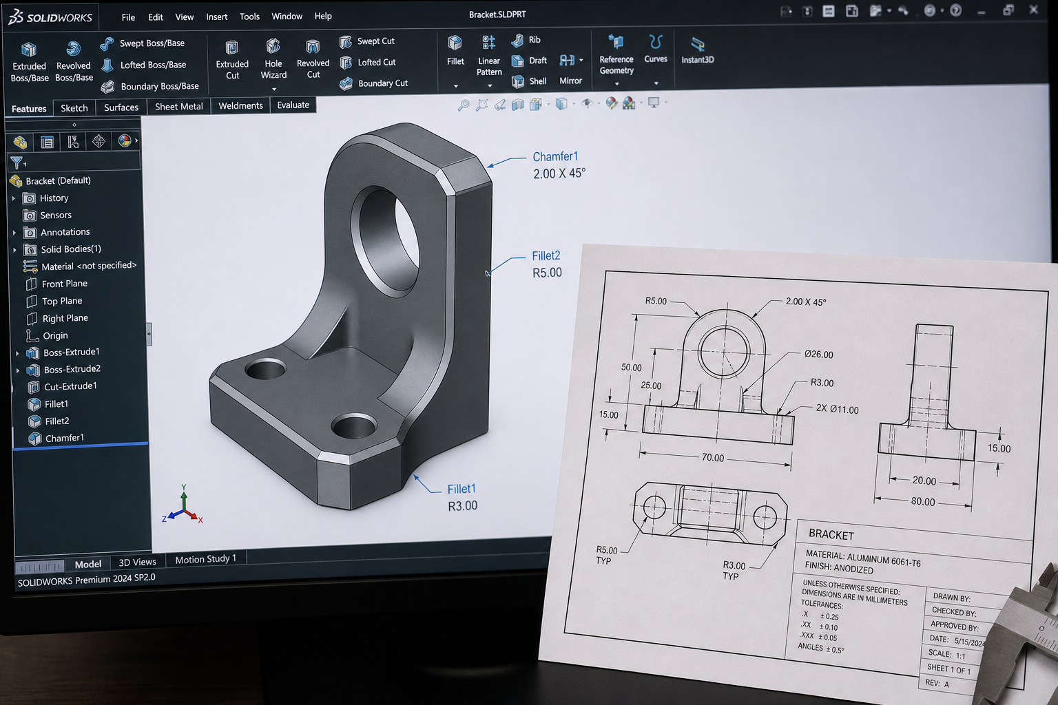
Introduction: Why fillet and chamfer design is so important
In the design of 3D printed parts, fillet and chamfer are not only aesthetic considerations, but also key design elements that affect the structural strength of the part, printing success rate and post-processing efficiency. Compared with traditional CNC machining, the 3D printing process has its unique advantages and limitations in sharp angle processing. This article will systematically analyze the design principles of fillets and chamfers in 3D printed parts from the perspective of engineering practice, helping engineers make more reasonable decisions in design.
Stress concentration principle and failure analysis of 3D printed parts
Material mechanics research shows that the stress concentration coefficient inside the part is closely related to the geometric shape. When the part is under load, the stress concentration factor at the acute angle can reach 3-5 times, which means that even if the overall safety factor is sufficient, the acute angle area may still become the starting point of fatigue cracks. In 3D printing, due to the characteristics of layered manufacturing, the interlayer bonding force at acute corners is naturally weak, further amplifying the risk of stress concentration. According to statistics on failure cases, about 65% of structural failures of 3D printed parts occur in acute angle areas. Therefore, in 3D printing design, reasonable fillet and chamfer design is not optional, but a necessary safety measure. The fillet radius should be determined according to the load direction and size during design. It is generally recommended that the minimum fillet radius should not be less than 25% of the wall thickness of the part.
Minimum fillet radius specifications in SLA and SLS processes
There are significant differences in the requirements for fillet radius between different 3D printing processes. For the SLA light curing process, due to the isotropic characteristics of resin curing, the minimum fillet radius is recommended to be no less than 0.5mm. In the SLS nylon sintering process, the characteristics of powder sintering allow the minimum fillet radius to be reduced to 0.3mm, but attention needs to be paid to the problem of powder residue. Due to the layering effect in the FDM fused deposition process, the fillet radius is recommended to be no less than 0.8mm. In the metal SLM process, due to the existence of thermal stress, the fillet radius should be no less than 1.0mm, and it is recommended to use a gradual transition rather than a fixed radius to disperse the concentration of thermal stress. The empirical value summarized by lantu3D in actual projects is: the fillet radius of load-bearing parts should not be less than 1.5mm, and the radius of non-load-bearing parts should not be less than 0.8mm. These values have been verified by hundreds of projects and have high reliability.
Application of chamfer design in assembly and post-processing
Chamfer design has multiple practical values in 3D printed parts. First of all, in assembly scenarios, a 1-2mm chamfer can significantly improve the assembly experience of shaft hole fit and reduce the probability of parts getting stuck. Secondly, in the post-processing process, the chamfer design can reduce the difficulty of grinding and polishing and avoid material accumulation at sharp corners. For surface treatments that require anodizing or painting, the chamfer design helps provide even coating coverage. Practice shows that reasonable chamfer design can reduce post-processing hours by 30-50%, while significantly improving the appearance quality of the final product. In addition, the chamfer design also helps to reduce the use of printing supports. When feasible, using chamfers instead of fillets can reduce the support contact area and facilitate subsequent removal. For the starting end of the external thread and the orifice, chamfer design is even more essential, which can effectively prevent thread chipping and orifice cracking.
Engineering case: the complete process from acute corner failure to rounded corner optimization
When an auto parts company developed an engine bracket, the initial design adopted multiple acute-angle transitions (radius 0.2mm). Cracks appeared in the first round of printed samples during the vibration test, and the failure locations were all concentrated in the acute angle area. By optimizing the transition radius to 1.5mm and adopting a gradient fillet design, the second round of samples successfully passed 2 million vibration fatigue tests. This case also found that the fillet optimization not only improved the structural strength, but also unexpectedly improved the printing quality - the support structure was easier to remove and the surface roughness was reduced by about 25%. This improvement reduces the post-processing time of a single piece from 45 minutes to 28 minutes. Based on an annual output of 5,000 pieces, it can save about 1,400 hours of work per year. The company’s experience has been incorporated into its 3D printing design standards, which require the transition radius of all load-bearing parts to be no less than 1.0mm. This case fully demonstrates that fillet and chamfer design is not only related to product performance, but also directly affects production efficiency and manufacturing costs.
Design checklist and common mistakes
In order to ensure the quality of the fillet and chamfer design of 3D printed parts, it is recommended to conduct the following inspections after the design is completed: First, confirm that transition fillets are set at all acute corners (
Submit a model, drawing, image or written notes. Engineers will review material, process, finishing and delivery based on actual use.