
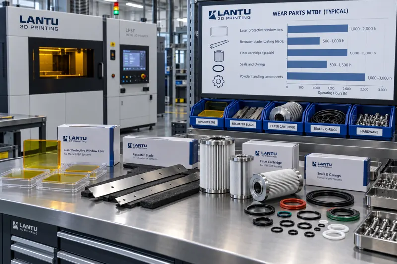
Introduction: Equipment Downtime Is Often Caused Not by a Major Assembly, but by One Protective Window
In metal and polymer additive manufacturing workshops, the failures that truly disrupt delivery schedules usually do not occur in expensive assemblies such as lasers, galvanometers, or recoater axes. Instead, they occur in protective windows costing anywhere from a few to several hundred yuan, recoater blades, filters, and seals. When a protective window contaminated by spatter sees its transmittance fall from 99% to 92%, the actual laser energy reaching the powder bed is reduced by approximately 7%, causing a continuing drift toward lack-of-fusion defects and balling in built parts. A recoater blade with 0.05 mm of edge wear can widen powder-layer thickness uniformity from ±8 μm to ±25 μm, doubling the standard deviation of density within the same production batch. Although these wear parts have low unit costs, they occupy critical positions in the energy, powder-bed, and environmental process chains, and their condition directly determines the baseline of build quality.
lantu3D has observed a common pattern across multiple volume-production projects: equipment records include the machine model, purchase year, and depreciation method, but do not record cumulative exposure hours for protective windows, cumulative recoating distance for blades, or filter differential-pressure curves. Wear parts are therefore replaced only after failure, resulting in unplanned downtime and batch-to-batch quality variation. Managing wear parts as measurable and predictable engineering assets is essential for additive manufacturing operations moving from merely being capable of production to delivering stable production.
1. Classification and Failure Mechanisms of Wear Parts
Wear parts in additive manufacturing equipment can be divided into three categories according to their functional process chain. The first category comprises optical-path components, including laser protective windows, galvanometer protective windows, and focusing-lens protective covers. Their failure mechanisms include reduced transmittance and localized thermal-lens effects caused by deposits of spatter and condensate. The replacement criterion is not visible damage, but transmittance below a specified threshold or the presence of non-removable carbonized spots on the surface. The second category comprises powder-bed process components, including recoater blades, recoater pressure plates, powder-cylinder sealing strips, and screens. Their failure mechanisms are abrasive wear and edge dulling; criteria include increasing edge radius, rising recoating resistance, and deteriorating powder-layer thickness consistency. The third category comprises environmental and auxiliary-process components, including filter elements, dust-collector cartridges, recirculating-water filters, inert-gas purification tubes, seals, and hoses. Their failure mechanisms include clogging, aging, and permeation; criteria include rising differential pressure, excessive leak rates, and drifting moisture or oxygen readings.
These three categories share a common characteristic: their degradation processes are continuous and measurable, while their consequences can be severe when failure occurs. Transmittance, edge wear, differential pressure, and leak rate are all continuous variables. Once measurement methods and thresholds are established, replacement can shift from failure-driven intervention to replacement before the threshold is exceeded.
2. Establishing Quantified Replacement Baselines with MTBF and MTTR
Replacement intervals should not be based solely on default recommendations in supplier manuals; they should be derived from measured data collected under actual shop-floor conditions. Two engineering metrics can be used to establish the baseline. MTBF, or mean time between failures, describes the operating hours from commissioning of a wear part until a replacement criterion is triggered. MTTR, or mean time to repair, describes the total duration from the replacement decision to restoration of equipment availability, including spare-part retrieval, removal and installation, cleaning, and reinspection.
The recommended approach is to establish a service-life record for every critical wear part. Data fields should include commissioning time, cumulative exposure hours or recoating distance, measurement values from each inspection, replacement reason, and first-part verification results after replacement. After collecting 10 to 20 replacement records, the MTBF distribution for that component under local operating conditions can be calculated, and a lower percentile can be selected as the preventive replacement interval. For example, if a protective window has a measured median MTBF of 320 hours and a standard deviation of 60 hours, the preventive replacement threshold can be set at 260 hours, enabling replacement before failure in approximately 85% of cases. At the same time, an immediate replacement criterion of transmittance below 95% should be retained, with whichever condition occurs first taking precedence.
MTTR is equally important. If a filter element has a measured MTTR of 95 minutes while a production line operates on a 40-minute takt time, one unplanned replacement will delay more than two batches. MTTR should be broken down into spare-part availability, removal and installation labor, and reinspection time, with each segment reduced separately. In many cases, total time can be reduced to less than 30 minutes. The greatest benefit usually comes from placing spare parts in designated storage locations beside the machine rather than locking them in a central warehouse.
3. Using Fault Tree Analysis to Identify True Bottleneck Components
Not all wear parts warrant the same level of management effort. Fault tree analysis (FTA) can break a downtime event into basic events and rank them by occurrence frequency and consequence severity. The top event can be defined as unplanned downtime exceeding four hours, then decomposed into optical-path failure, powder-bed process failure, environmental and auxiliary-process failure, and control-system failure, followed by further decomposition into specific components and criteria. For each bottom event, three values should be tracked: annual occurrence count, average MTTR, and resulting quality-risk level.
In one metal AM production line, fault-tree ranking showed that protective windows and recoater blades accounted for approximately 62% of total downtime, while filters and seals accounted for about 21%, with the remainder attributable to electrical and software issues. Management resources were therefore focused on the first two categories: protective windows were supported by two-window rotation and an offline cleaning station, while recoater blades were supported by spare edges and quick-location fixtures. Annual unplanned downtime was reduced by approximately 40%. This prioritization-before-investment approach avoids the common problem of allocating budget evenly across all spare parts with little practical benefit.
4. Closed-Loop Verification After Replacement: Standard Coupons and Interim Checks
Wear-part replacement is not the end of the process; it is the start of quality verification. Following any replacement of an optical or powder-bed component, post-replacement verification must be performed by printing or inspecting a standard coupon and using metrics comparable with historical data to determine whether the machine has returned to its baseline condition. The standard coupon should have fixed geometry, material, and placement location. Its inspection items should include, at minimum, density, critical dimensions, surface roughness, and melt-track morphology, with the data stored in the same trend chart.
Measuring instruments themselves also require interim checks. Power meters used to assess transmittance, microscopes used to assess blade-edge wear, and differential-pressure gauges used to assess pressure drop should all have interim verification points established between external calibrations. Stable check artifacts should be used to confirm whether their readings have drifted. Otherwise, a hidden issue may arise: the equipment has actually recovered, but instrument drift causes a false judgment and another unnecessary replacement, wasting production capacity.
5. Spare-Parts Strategy: From Purchasing After Failure to Classified Inventory
Wear-part inventory strategy should be linked to MTBF and procurement lead time. Components can be managed in three tiers. Tier A includes parts with high MTTR, long lead times, and severe downtime consequences, such as galvanometer protective-window assemblies and specialized recoater blades. Maintain a minimum on-site inventory of one unit and replenish on a rolling basis according to the preventive replacement interval. Tier B includes parts with stable consumption and convenient procurement, such as protective windows, filter elements, and seals. Set minimum and maximum inventory levels based on monthly consumption and replenish automatically. Tier C includes universal standard parts, such as hoses, fittings, and standard O-rings; retain only the minimum necessary variety without carrying excess inventory.
Batch traceability for wear parts should also be established. Initial transmittance values for a batch of protective windows and blade-edge inspection results for a batch of recoater blades should be linked to quality data generated during their use. If a particular batch causes systematic shifts in build quality, the affected batch can be quickly identified and replaced rather than investigated component by component.
Conclusion
Equipment stability is not determined by the most expensive component, but by the weakest link. Upgrading protective windows, recoater blades, filters, and seals from reactive consumables replaced only after failure into engineered assets with MTBF baselines, quantified criteria, post-replacement verification, and classified inventory is a prerequisite for AM workshops to turn capacity commitments into reliable deliveries. Within its full-lifecycle delivery system, lantu3D manages wear-part condition together with batch quality data, ensuring that every maintenance action is traceable, evaluable, and continuously improvable.
Invia un modello, un disegno, un'immagine o note scritte. Gli ingegneri valuteranno materiale, processo, finitura e consegna in base all'uso effettivo.