
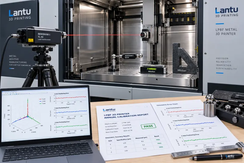
Introduction: A Machine That Is Still Printing Is Not Necessarily Still Within Its Accuracy Range
In many workshop equipment records, a metal 3D printer may have been in operation for three years without any systematic geometric accuracy inspection beyond the replacement of consumable components. It continues to produce parts, and occasional spot checks of dimensional reports pass, so it is considered healthy. However, during one production delivery, the true position of hole patterns across parts from the same batch showed a systematic deviation of 0.18 mm. Traceability analysis found that the issue was neither process parameters nor powder batch variation: positioning error in the middle of the Z-axis travel had accumulated to 0.09 mm, while perpendicularity deviation in the recoating plane amplified interlayer misalignment layer by layer. The machine had not “failed”; it had simply drifted outside its accuracy band.
Geometric accuracy inspection and annual calibration address precisely this hidden risk of equipment that remains operational but has lost accuracy. They transform machine accuracy from a subjective impression into measurable, assessable, and compensable engineering data.
1. What Exactly Should Be Measured for Geometric Accuracy?
The geometric accuracy of 3D printing equipment is not a single metric, but a set of data composed of several independent error sources. The following categories generally require attention in engineering practice:
Linear positioning accuracy and positioning repeatability: A laser interferometer is used to measure multiple points over the full travel of each axis and generate a positioning error curve. Positioning repeatability indicates how consistently the machine returns to the same location and should generally be significantly better than positioning accuracy. This is particularly critical for multi-laser stitching and large-format builds.
Backlash: Clearance between the lead screw and nut or within couplings appears as lost motion during direction reversal. Z-axis backlash directly changes the actual layer thickness, resulting in poor interlayer bonding or dimensional stepping; backlash in the recoating axis affects powder spreading uniformity.
Perpendicularity and straightness: Perpendicularity between the build-cylinder motion direction and the recoating plane, along with straightness deviations of guideways over the full travel, can accumulate as tilt along the part height direction.
Build-platform flatness and levelness: An unlevel build plate causes the gap between the recoater blade and powder bed to vary along its travel. At best, this produces uneven powder spreading; at worst, it scratches previously formed layers.
These error sources are independent of one another. They cannot be replaced by a single “overall accuracy” value, nor can a machine be deemed qualified by measuring only one of them.
2. Selection and Application Levels of Inspection Tools
Different machine accuracy classes and inspection objectives require tools of appropriate capability. Using ultra-high-precision instruments indiscriminately only increases cost and management burden.
Laser interferometer: Used to measure and compensate linear positioning accuracy, repeatability, and pitch error. It is the primary tool for annual calibration. During measurement, corrections for ambient temperature and material thermal expansion coefficients are essential; otherwise, readings themselves will be contaminated by environmental error.
Ballbar system: Used to rapidly assess the circular trajectory generated by coordinated two-axis motion. It can reveal backlash, servo following error, perpendicularity mismatch, and other interpolation-related issues in a single test, making it suitable for monthly or quarterly trend monitoring.
Precision level and granite square: Used for preliminary checks of build-platform levelness and column perpendicularity. These tools are low-cost and quick to operate, making them suitable for routine inspections.
Standard test artifacts: Geometric test parts produced and measured according to a standardized design convert machine condition into physical evidence that can be archived and compared across years.
The tool-selection principle is straightforward: use lower-level tools for daily trend observation and higher-level tools for annual assessment and compensation.
3. Annual Calibration Execution Process
A compliant annual calibration should be reproducible rather than arranged ad hoc based on experience. The following sequence is recommended:
Step 1: Confirm environmental conditions and reference conditions. Calibration should be performed after the machine has reached thermal equilibrium, and ambient temperature and humidity must be recorded. Foundation settlement, machine relocation, and changes in nearby vibration sources should also be noted in the report, as they are error sources in their own right.
Step 2: Measure the full travel range. Measure each axis at equally spaced points in both directions, recording forward and reverse readings to calculate backlash and generate positioning error curves.
Step 3: Compensate errors. Load the measured pitch-error table into the control system, then adjust backlash parameters. Measurements must be repeated after compensation to confirm that the error band has converged within the target range. Compensation without verification is simply an unverified modification.
Step 4: Validate using test artifacts. Print standard test artifacts and inspect them using coordinate measuring equipment. Compare instrument data with actual build results to confirm that compensation is effective under real operating conditions.
Step 5: Archive results and issue a conclusion. Produce a calibration report with a clear disposition: qualified, restricted use, or removed from service for corrective action. Any restricted-use status should specify the limitations, such as permitting builds only within the central area of the build envelope.
4. How to Set Calibration Intervals Without Guesswork
Many companies set a fixed annual calibration interval, yet equipment utilization can vary substantially. A more rational approach is to tier intervals according to operating load:
For machines operating at full load in continuous multi-shift production, laser interferometer calibration is recommended every six months, with ballbar trend monitoring every quarter. Medium-load machines can undergo annual calibration with ballbar monitoring every six months. For low-load machines or those primarily used for prototype production, annual calibration is generally sufficient; however, additional inspection is mandatory after relocation, restart following an extended shutdown, a collision, or abnormal vibration.
Event-triggered calibration often prevents risks more effectively than periodic calibration. Mechanical deformation after a collision, foundation adjustment, and changes in lubrication condition after prolonged downtime are all typical causes of abrupt accuracy shifts.
5. Common Misconceptions and Countermeasures
Misconception 1: Measure only, without compensation. Archiving an error curve without entering it into the compensation table turns inspection into a recordkeeping exercise. Measurement must be closed-looped through parameter correction and repeat measurement.
Misconception 2: Look only at individual values, not trends. A single positioning error of 0.05 mm may be within tolerance, but three consecutive results of 0.02, 0.035, and 0.05 mm indicate rapid wear of the lead screw or guideways. Trends are more valuable than isolated readings.
Misconception 3: Misidentify process issues as equipment issues, or vice versa. Dimensional deviations may result from thermal-stress distortion or from machine inaccuracy. A useful criterion is that deviations reproducible across machines, build areas, and materials generally indicate a process issue, whereas deviations occurring only on one machine or in one area point to the equipment.
Misconception 4: Disconnect calibration reports from application. Calibration conclusions are not communicated to production scheduling and process personnel, so machines in restricted-use status continue to accept high-precision orders. Calibration conclusions should become a technical criterion in order review.
Conclusion
The value of geometric accuracy inspection and annual calibration is not to make equipment appear more professional. It is to turn the question, “Can this machine still fulfill this order?” into an evidence-based decision. A recommended approach is to use laser interferometry for annual assessment and compensation, ballbar testing for quarterly trend monitoring, and standard test artifacts for physical records, supported by event-triggered follow-up inspections and integration of calibration conclusions into order reviews. In this way, machine accuracy becomes a genuine part of delivery capability rather than merely a machine self-check statement.
Invia un modello, un disegno, un'immagine o note scritte. Gli ingegneri valuteranno materiale, processo, finitura e consegna in base all'uso effettivo.