
Introduction: Build Defects Are Often Attributed to Energy Parameters, but Their Root Cause Is Often Powder Spreading
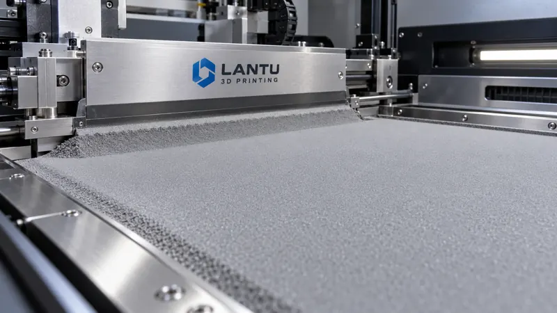
In metal laser powder bed fusion (LPBF) production, when lack-of-fusion defects between layers, localized warping, or abnormal surface roughness occur, engineering teams typically first adjust laser power, scan speed, and hatch spacing. However, reviews of numerous production batches show that a considerable proportion of issues do not originate from energy input, but from the powder layer itself: uneven spreading produces locally thin or thick layers, recoater edge wear creates drag streaks across the powder bed, and powder agglomeration creates voids. Because powder-layer thickness directly determines the effective volumetric energy density, a thickness deviation of 30 μm can be enough to invalidate an otherwise qualified process window. Bringing powder spreading quality and recoater condition under controlled management is therefore a key step in advancing process stability from experience-based parameter tuning to predictable production release.
1. How Powder-Layer Quality Determines Melt-Track Formation
The key powder-layer metrics are thickness consistency, packing density, and surface flatness. For commonly used spherical powders in the 20–63 μm range, the nominal layer thickness is generally set to 30–60 μm, while the actual effective layer thickness is jointly affected by powder flowability and spreading speed. Where the powder layer is locally too thin, laser energy becomes relatively excessive, increasing the risk of keyholing and spatter; where it is too thick, energy is insufficient and the melt track cannot penetrate into the previous layer, resulting in lack of fusion. Low packing density means greater void content between powder particles, increasing shrinkage after melt-pool solidification and causing uneven surfaces and adhered powder. In engineering practice, the “powder-layer density ratio” can be used as a monitoring metric: measure the powder mass spread per unit area from the same powder batch at the same recoater speed. If variation exceeds ±5%, production should be stopped for investigation.
2. Recoater Type Selection and Edge Condition Management
Common recoaters are divided into rigid blades—made from high-speed steel, ceramic, or cemented carbide—and compliant recoaters, such as rubber blades, silicone blades, and brushes. Rigid blades provide high powder-layer density and good repeatability, but are sensitive to oversized particles and spatter. If hard inclusions are encountered, they can drag continuous grooves across the powder bed or even damage already built areas. Compliant recoaters offer greater fault tolerance, but their edges wear more rapidly, causing powder-layer thickness to gradually increase during prolonged operation. Selection should be based on powder morphology and part characteristics: high-melting-point alloys and materials with a high spatter tendency are better suited to compliant recoaters to reduce dragging risk, whereas high-volume parts requiring tight dimensional consistency are better suited to rigid blades combined with strict edge inspections.
Recoater edge condition must be quantified. It is recommended to establish an edge-inspection card: after every 40–80 operating hours or upon completion of each production batch, use optical magnification or a profilometer to inspect edge straightness and chipping. The blade should be replaced if visible chips appear, the edge radius exceeds 20 μm, or periodic streaking is observed on the powder bed after spreading. Cumulative operating hours and replacement reasons should also be recorded to establish blade-life data.
3. Coordinated Setting of Powder-Spreading Process Parameters
Powder-spreading speed, recoater clearance, and powder feed quantity must be coordinated. Excessive spreading speed can cause powder to bounce and produce sparse layers; excessively low speed reduces equipment throughput and may compact the powder bed, causing local density variation. An engineering reference range is 40–120 mm/s, to be determined in combination with measured Hall flow rate and apparent density. For reclaimed powder with poor flowability, speed should be reduced and powder feed increased appropriately. Recoater clearance is generally set at 1.5–2 times the layer thickness. Too little clearance can cause interference between the recoater and the built surface, while excessive clearance can create an overly loose and thick powder layer. The parallelism between the powder-spreading platform and build-cylinder plane should also be calibrated regularly; a parallelism deviation exceeding 50 μm can result in a wedge-shaped powder-layer distribution across the entire build plate.
4. The Direct Effect of Powder Condition on Spreading
Powder particle-size distribution, satellite-particle content, moisture content, and flowability are input conditions for powder-layer quality. After repeated reuse cycles, the proportion of satellite particles and fractured particles in reclaimed powder increases, Hall flow rate declines, and agglomeration and dragging are more likely during spreading. For each batch of recycled powder, it is recommended to test D10/D50/D90 particle-size distribution, apparent and tapped density, and Hall flow rate, while defining a maximum number of reuse cycles and a virgin-to-reclaimed powder blending ratio. Excessive powder moisture can cause adhesion at the recoater leading edge and intermittent powder starvation on the bed. Storage-environment relative humidity should therefore be controlled and powder moisture content monitored.
5. Process Monitoring and Closed-Loop Response to Abnormalities
Parameter settings alone are insufficient to ensure consistency; the powder-spreading process must be made observable. Practical solutions include powder-bed imaging systems that capture an image of every layer to identify streaks, powder shortages, and accumulated spatter particles; laser displacement sensors or optical thickness-measurement points above the build cylinder for sampled powder-layer thickness measurements; and gravimetric powder-layer witness coupons for critical batches. When the monitoring system detects abnormal layers consecutively, it should trigger a pause and manual verification rather than allow printing to continue and create irreversible defects. All abnormalities should be recorded by layer number, location, image, and disposition result, then included in the batch quality record to support subsequent traceability and parameter correction.
6. Establishing Standard Operating Procedures and Acceptance Checklists for Powder Spreading
It is recommended that powder-spreading management be formalized into an executable checklist, including: recoater edge inspection and cleaning before startup; confirmation of powder-hopper inventory and continuous powder supply; records of platform parallelism and recoater-clearance verification; powder-bed image confirmation for the first layer; powder-layer quality spot-check data for every batch; registration of reclaimed-powder batch numbers and reuse cycles; and recoater edge replacement records with root-cause analysis. The checklist should be a prerequisite for batch release, rather than supplementary documentation prepared after the fact.
Conclusion
The powder-spreading stage sits at the intersection of powder condition, equipment condition, and energy input, and its variations are amplified by subsequent melt-pool processes. By connecting powder-layer thickness consistency, recoater edge condition, coordinated spreading parameters, powder reuse management, and process monitoring into a controlled chain, companies can move defect investigation upstream from the final outcome to the root cause, significantly reducing trial-and-error costs and batch scrap rates. For additive manufacturing service providers focused on reliable delivery, powder-spreading quality management is not an auxiliary operation; it is a fundamental component of process capability.
Invia un modello, un disegno, un'immagine o note scritte. Gli ingegneri valuteranno materiale, processo, finitura e consegna in base all'uso effettivo.