
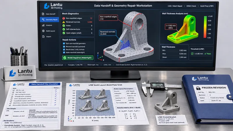
Introduction: Why Can the Same Model File Produce Different Results on Two Machines?
In 3D printing orders, the most underestimated risk is not machine capability, but data handover between the customer’s design model and machine setup. One batch of aluminum alloy brackets passed in a single build on Machine A, but developed localized thin-wall loss after being transferred to Machine B. The model filename and revision appeared identical, yet one file was a repaired, watertight shell while the other still contained non-manifold edges and reversed normals; the slicer’s default unit was also interpreted as inches rather than millimeters. Rework took two days, with powder and machine-time losses of approximately CNY 3,800. lantu3D classifies such issues as lifecycle management from blueprint/design to physical delivery: a model is not an attachment, but an engineering input that must be validated, frozen, and traceable.
1. Minimum Fields Required in a Data Handover Package
A build-ready handover package is not simply an arbitrarily named compressed folder. It should contain at least six categories of items: the original model (STEP/STL/3MF), the repaired manufacturing model, material and process codes, revision and hash information, coordinate-system and unit declarations, and inspection and release records. It is recommended to formalize these fields in a JSON manifest: project_id, part_revision, source_file, manufacturing_file, sha256, unit=mm, axis_convention, material_grade, process_code, build_orientation, checklist_result, approver, and freeze_time. 3MF is preferable to plain STL because it can carry units, colors, materials, and lattice metadata. If STL must be used, units and coordinate systems must be documented in an accompanying manifest rather than relying on operator memory.
2. Geometry Repair: Turning “Can Be Opened” into “Can Be Printed”
Printability validation should cover at least seven items: a watertight closed shell, consistent normals, no non-manifold edges or self-intersecting triangles, minimum wall thickness at or above the process threshold, minimum feature size at or above the resolvable value after laser-spot or nozzle compensation, overhang angle and support accessibility, and assembly clearances and post-processing allowances. For LPBF metal parts, the recommended design wall thickness is at least 0.8 mm, while thin-wall tips should use a 0.3–0.5 mm fillet transition. For polymer FDM with a 0.4 mm nozzle, standalone boss widths should generally not be less than 0.8 mm. Chordal deviation should preferably be controlled within 0.01–0.05 mm to prevent high-curvature surfaces from being overly simplified by triangular facets. All repair actions must be recorded, including removal of floating fragments, stitching of open edges, normal unification, localized thickening, and support-base generation. Each step should be entered in check_result, with before-and-after hashes retained. Manufacturing models must not be overwritten with stateless filenames such as “final_v2_new.stl.”
3. Freezing Units, Coordinate Systems, and Build Layouts
Three cross-checks must be completed before machine setup: compare model bounding-box dimensions against the engineering drawing title block, compare slicer-preview layer thickness against the process card, and compare the machine build-chamber coordinate system against the placement matrix. Common pitfalls include CAD exports that treat millimeters as dimensionless values, STL files scaled by 25.4 times when interpreted in inches, and multiple parts in a shared build intruding into one another’s support zones. A layout.csv should be generated for every build, including: part_id, rotation_x/y/z, translation_x/y/z, support_volume, estimated_build_time, and powder_bed_utilization. Maintain powder-removal channels of at least 3 mm between parts in a shared build, and retain observable openings for complex internal flow channels. Any layout change must generate a new layout revision; old revisions should be marked obsolete rather than deleted, enabling reconstruction of historical delivery conditions.
4. Build Release Gates and the Evidence Chain
Release does not mean that “the slicer reported no errors.” It means that all four gates have passed: D1, the data gate (hash consistency, units, watertightness, wall thickness, and normals); D2, the process gate (material lot number, parameter-package revision, valid machine calibration, and oxygen-content/dew-point records); D3, the layout gate (placement, supports, powder-removal channels, and shared-build cost-allocation rules); and D4, the approval gate (dual sign-off by process engineering and quality inspection, plus freeze time). Use decision tables rather than verbal confirmation: a measured minimum wall thickness of 0.82 mm against a 0.80 mm requirement is PASS; one non-manifold edge is FAIL and requires return to the repair step; incompatibility between the parameter package and machine firmware prohibits job release. Release records should follow ALCOA+ principles: attributable, legible, contemporaneous, original, and accurate, supplemented by complete, consistent, enduring, and available records.
5. Implementation Checklist and Common Failure Modes
Begin implementation with a 10-minute handover checklist: ① Do filenames and revision numbers include project_id and part_revision? ② Does sha256 match the requirement freeze sheet? ③ Is the unit explicitly declared as mm? ④ Is the shell watertight? ⑤ Do all normals point outward? ⑥ Are non-manifold edges and self-intersections both zero? ⑦ Are measurement screenshots attached for minimum wall thickness and minimum features? ⑧ Does the build layout include rotation and translation matrices? ⑨ Are the parameter-package hash and machine-calibration validity period recorded? ⑩ Is the release conclusion written into a non-overwritable log? Common failures include customers sending only messaging-app screenshots after a design revision, unrecorded repair actions that make recurring issues impossible to trace, different default compensations for the same STL across slicers, and reuse of an old layout after rework, resulting in support damage. It is recommended to audit five delivered project handover packages every month and track the first-build pass rate and the proportion of data-related rework, targeting at least 95% and no more than 2%, respectively.
Conclusion
The essence of a model data handover package is translating design intent into a manufacturing language that machines can execute, quality teams can verify, and organizations can trace. lantu3D focuses not on one successful print, but on ensuring that every status change from blueprint to physical delivery has evidence: geometry is verifiable, units are unambiguous, revisions do not drift, and release is controlled by gates. Moving validation upstream, before machine setup, reduces more than a single rework event; it reduces systemic uncertainty when replicating processes across machines, batches, and teams.
Invia un modello, un disegno, un'immagine o note scritte. Gli ingegneri valuteranno materiale, processo, finitura e consegna in base all'uso effettivo.