
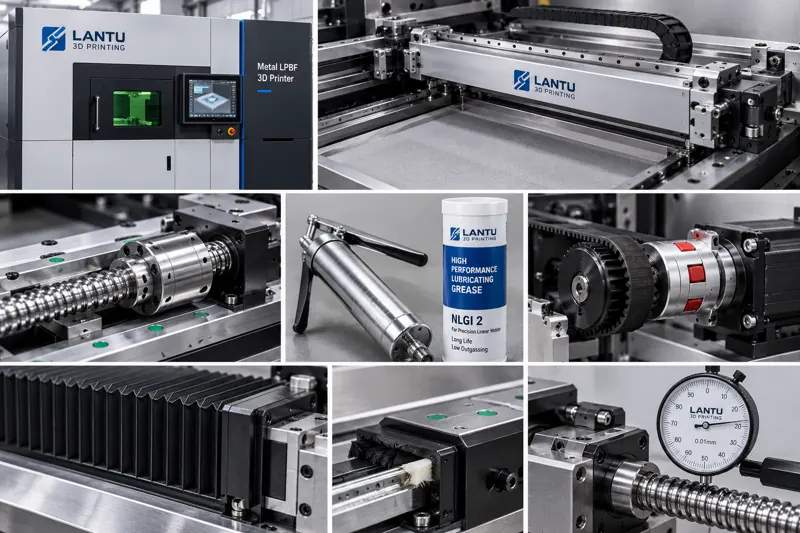
Introduction: When the Optical Path Is Accurate but Prints Are Not, the Problem Is Often Mechanical
Calibration records in most additive manufacturing facilities focus on laser power, galvanometer zero position, and protective-window transmittance—and rightly so. However, when a machine passes optical calibration but standard test coupons still exhibit layer misalignment, serrated contours, or dimensional deviations along long travel axes, experience points to one common cause: the mechanical transmission chain. The reciprocating motion of the recoater blade, Z-axis lifting, build-cylinder descent, and even the scanning galvanometer all contribute positioning errors that ultimately accumulate in the part. Mechanical instability is characterized by gradual degradation. Unlike optical components, which can fail suddenly, transmission components wear incrementally at the micron level; by the time an out-of-tolerance dimension is detected, an entire batch of parts may already have been affected. This requires a maintenance approach based on a different logic from optical maintenance: not “replace it when it fails,” but “use condition data to determine when intervention is required.”
1. First Distinguish the Three Types of Motion Pairs: Rolling, Sliding, and Flexible Transmission
The motion pairs on a metal powder bed fusion machine that should be included in maintenance records generally fall into three categories. The first comprises rolling linear guideways and ball screws, which provide high-precision lifting of the build platform and linear reciprocating motion of the recoater. Typical repeat positioning accuracy requirements are on the order of ±5 μm, with travel distances of 300–500 mm. The second category comprises sliding or semi-dry friction pairs, such as wear strips on recoater guideways, sealing guide bands on build-cylinder walls, and polyurethane sealing rings on powder-feed pistons. These contain no rolling elements and rely on material pairing and a lubricating film; their wear rates are highly sensitive to powder contamination. The third category is flexible transmission, including timing belts, couplings, and gearbox input ends, which transfer servo-motor torque to the actuated end. Their failure modes are not primarily wear, but elastic deformation and increased backlash.
The failure indicators for these three component types differ and cannot be assessed using the same criteria. Rolling-pair failure is indicated by increased reversal backlash and noise; sliding-pair failure by increased motion resistance and sticking; and flexible-transmission failure by synchronization errors and phase drift. Recording them separately in the maintenance system is a prerequisite for establishing meaningful subsequent criteria.
2. Ball Screws and Guideways: Turning “Backlash” into a Measurable Value
Ball-screw axial backlash is the most direct parameter to quantify. A commonly used engineering method is dial-indicator reverse-travel measurement: fix the indicator base at the mid-position of the build platform, command an upward movement of 0.5 mm, then reverse back to the original position and record the unrecovered displacement. Newly installed equipment typically measures 0.005–0.015 mm. When the reading consistently exceeds 0.03 mm and recurs within the same travel section, the raceway or nut preload in that section has likely deteriorated, and preload adjustment or replacement parts should be scheduled. The key is not to measure once, but to measure under the “same position, same load, and same direction”; otherwise, the data cannot be compared.
Guideway criteria depend more heavily on resistance and noise. Use a torque wrench or push-pull force gauge to pull the recoater uniformly along its travel and record the fluctuation in resistance over the full stroke. In a healthy condition, the fluctuation should remain within ±10% of the average value. If a distinct peak occurs in a specific section, first investigate powder ingress and grease hardening in that section rather than immediately declaring the guideway unserviceable. Trends in the frequency spectrum of operating noise should also be recorded, as metallic abnormal noise often appears weeks before dimensional tolerances are exceeded.
3. Lubrication Management: Not “More Grease,” but the Correct Amount at the Correct Interval
Lubrication is one of the most oversimplified aspects of mechanical maintenance. Rolling linear guideways typically use NLGI Grade 2 lithium-based grease, and the replenishment volume per application is very small. For a guideway with a 400 mm stroke, for example, 0.3–0.6 cm³ per carriage is sufficient. Excess grease can instead form sludge and attract metal powder, accelerating abrasive wear. Relubrication intervals should be based on travel distance rather than calendar time: once every cumulative 100 km of reciprocating travel or every equivalent 400–600 operating hours is more representative of actual wear than “once per month.”
Environmental conditions must also be considered when selecting grease. Equipment chambers contain inert-gas circulation and fine metal powder. Extreme-pressure greases containing molybdenum or graphite can agglomerate in dusty environments, so a synthetic grease with moderate base-oil viscosity and no solid additives is preferable. Mixing greases from different brands or with different thickener types must also be avoided. Mixing lithium-based and polyurea-based greases can cause structural breakdown, manifested by oil separation and thinning of the grease. All lubrication points, grease grades, quantities, and intervals should be documented on a lubrication card linked to the equipment record, eliminating the inconsistency of having “whoever is available” add grease.
4. Dust Ingress: A Wear Multiplier Unique to Additive Manufacturing Equipment
Compared with general CNC machine tools, the greatest additional risk in powder bed systems is micron-scale metal powder. Once powder with a particle size of 15–45 μm bypasses seals and enters a raceway, it creates three-body abrasive wear, typically increasing the wear rate by an order of magnitude over a clean environment. The focus of protection is not “complete sealing,” which is unrealistic, but graded defense: the first level consists of labyrinth dust-exclusion structures at the recoater and build cylinder; the second consists of wipers at guideway ends and bellows covers; and the third consists of clean positive-pressure airflow in the equipment chamber.
From a maintenance standpoint, all three levels must be converted into inspectable items. Dust wipers are consumable components and their lip wear should be checked after 800 cumulative operating hours. Pinholes and cracks in bellows covers are visible to the naked eye and should be included in inspection checklists. Chamber positive-pressure values should be documented in shift handover records; when differential pressure falls below the specified threshold, the machine should be stopped immediately for investigation rather than waiting until powder has entered the raceway. One practical criterion is this: if metal-particle concentration in guideway grease samples continues to rise, the sealing barrier has failed. Replacing the grease can only provide temporary relief; the seals must be inspected at the same time.
5. Flexible Transmission and Servo Condition: Quantifying Backlash and Following Error
Timing-belt tension loss can create phase differences between two ends that should remain synchronized. On site, tension can be measured with a tension gauge, or simplified using the frequency method: pluck the belt span to measure its fundamental transverse vibration frequency and compare it with the baseline value recorded at installation. A deviation greater than 15% indicates that retensioning is required. The coupling elastomer connected to the belt is another weak point. Rubber or polyurethane elastomers can harden and crack under long-term cyclic loading; a visual inspection every 500 hours is generally sufficient.
Servo-side criteria are available in the drive: peak and average position following error. Under normal conditions, the following-error curve for the same motion program is stable. When this curve consistently shows elevated peaks at the same location, it usually indicates increased mechanical resistance—such as insufficient lubrication, guideway contamination, or excessive preload—rather than a servo-gain issue. The value of this signal is that it is free: no additional sensors are required, only periodic export and recording. When reviewed on the same trend chart as lubrication records and grease-change intervals, the mechanical degradation path becomes very clear.
6. Post-Maintenance Verification: Close the Loop with a Standard Part, Not the First Production Part
Every mechanical adjustment must include a verification step; otherwise, there is no way to determine whether maintenance improved performance or introduced a new deviation. A recommended practice is to retain a dedicated verification part: a test coupon incorporating long travel in both X and Y directions and representative thin-wall features, with stable dimensions and material consistent with routine production. Print this part after every mechanical maintenance event, measure key dimensions, and compare them with historical data. Production should be released only when the results fall within the historical mean ±1σ range.
This should be supported by a structured record. Every mechanical maintenance event should retain four elements: the component replaced or adjusted, measurement values before adjustment, measurement values after adjustment, and the verification-part identifier and measurement results. Only with all four elements can a subsequent dimensional anomaly be quickly determined to be either “a continuation of equipment degradation” or “an issue left over from the previous maintenance.” If any element is missing, troubleshooting reverts to guesswork.
Conclusion
Maintenance of mechanical transmission and motion components is fundamentally about converting “gradual degradation” into “measurable trends.” The core practices can be summarized in four points: maintain separate records by motion-pair type; establish backlash, resistance, and following error as recurring measurement items collected consistently under the same conditions; manage lubrication by travel distance and grease specification rather than experience; and always close the loop with a standard verification part after maintenance. In well-managed facilities, dimensional scrap caused by mechanical instability can be reduced to very low levels, and delivery is no longer interrupted by an unexpected guideway seizure. For additive manufacturing operations centered on small-lot, high-mix production, this predictability is itself the foundation of reliable delivery commitments.
Invia un modello, un disegno, un'immagine o note scritte. Gli ingegneri valuteranno materiale, processo, finitura e consegna in base all'uso effettivo.