
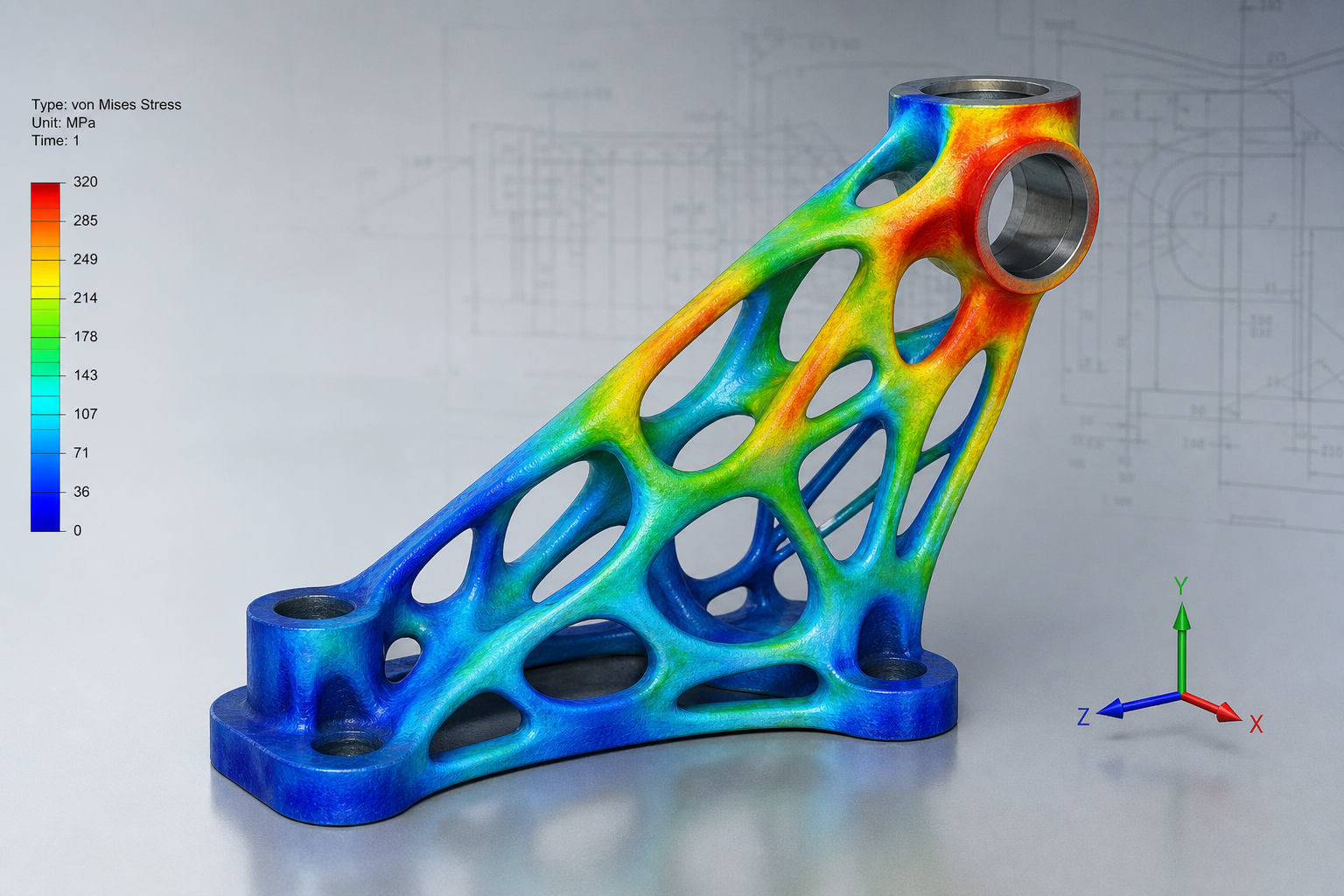
The Natural Fit Between Topology Optimization and 3D Printing
Topology optimization is a design method based on mathematical algorithms. Given a design space, load conditions, and constraint conditions, it searches for the optimal material distribution scheme. Unlike traditional experience-based design methods, topology optimization starts from a blank canvas and progressively removes inefficient material through computational iterations, ultimately producing an organic structural form with an optimal stiffness-to-weight ratio. This organic form often includes complex freeform surfaces, variable-density lattice-like structures, and internal cavities, which are exactly the kinds of geometries that 3D printing is best at producing. The combination of topology optimization and 3D printing is regarded as a classic example of design-manufacturing integration. In traditional manufacturing, topology optimization results are often difficult to realize, whereas 3D printing is not constrained by these limitations and can accurately reproduce any complex geometry generated by topology optimization.
Main Topology Optimization Algorithms and How to Choose Them
The mainstream topology optimization algorithms used in engineering today include the density-based method, the level set method, and bi-directional evolutionary structural optimization. The density-based method is the most mature commercial algorithm. By assigning each element a pseudo-density value between 0 and 1, it converts the discrete topology optimization problem into a continuous mathematical programming problem. The level set method describes structural boundaries through implicit surfaces and has advantages in maintaining smooth boundaries. Bi-directional evolutionary structural optimization evolves the structure by gradually adding and removing elements, offering an intuitive physical interpretation. When choosing an algorithm, the complexity of the design problem, available computing resources, and required result quality should all be considered comprehensively. For most mechanical part designs, the density-based method is already mature and reliable enough.
Key Parameters in Simulation Setup
The quality of topology optimization results depends heavily on the reasonableness of the simulation setup. The first task is to define the design space accurately, that is, the three-dimensional region where material may be distributed. The design space should be as large as possible to give the algorithm sufficient optimization freedom, while also excluding areas that do not need optimization. Second, the load and constraint conditions must realistically reflect the part’s operating state. Overestimating the load will lead to overdesign, while underestimating it may create safety risks. Mesh density is a key parameter affecting both calculation accuracy and efficiency. A mesh that is too coarse will lose geometric detail, while a mesh that is too fine will sharply increase computation time. It is recommended to use a refined mesh in critical areas and a coarser mesh in non-critical areas. The convergence criterion is also important; typically, when the change in the objective function is less than 0.1%, the optimization can be considered converged.
Interpreting Optimization Results and Geometric Reconstruction
The output of topology optimization is usually a density contour map, shown as a distribution of elements with different grayscale values within the design space. Areas with density close to 1 are where material should be retained, while areas with density close to 0 are where material can be removed. However, geometry generated directly from optimization results often contains gray-scale regions, jagged boundaries, and irregular surfaces, and cannot be used for manufacturing as is. Geometric reconstruction is the key step that converts optimization results into a manufacturable CAD model. Common methods include binarizing grayscale results through thresholding, generating smooth CAD surfaces through surface fitting or re-modeling techniques, and applying design rules to engineer the geometry. Modern CAD software has already integrated topology optimization modules, enabling the entire process from optimization to reconstruction to be completed automatically.
Manufacturability Validation and Print Preparation
The geometry generated by topology optimization must undergo manufacturability validation before fabrication. For 3D printing, the main validation items include minimum wall thickness checking, overhang angle checking, enclosed cavity checking, and whether the overall size exceeds the build volume of the printing equipment. During the print preparation stage, the optimal build orientation must be determined. Topology-optimized structures usually have complex anisotropic characteristics, and the choice of print direction directly affects mechanical performance, surface quality, and support requirements. It is recommended to orient the main load-bearing direction within the X/Y plane to take advantage of in-plane strength. Support structure design is also critical; the contact area between supports and the part should be minimized as much as possible. For fine lattice-like structures in particular, removing supports may damage thin-walled features.
Case Study: Optimization Practice for a Lightweight Bracket
Taking the end-effector bracket of an industrial robot arm as an example, the traditional design used aluminum alloy casting and weighed 2.3 kg. After topology optimization, the new bracket design weighed 1.1 kg, reducing weight by 52%, increasing the first natural frequency by 40%, and reducing the maximum stress by 15%. The key optimization steps included defining the design space as the original part’s envelope, applying operating loads, setting a volume fraction constraint, and using the density-based method to iterate toward an initial optimization result
Submit a model, drawing, image or written notes. Engineers will review material, process, finishing and delivery based on actual use.